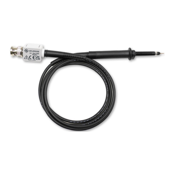
Summary of Contents for Rohde & Schwarz RT-ZP03S
- Page 1 Allice Messtechnik GmbH ® R&S RT-ZP03S Probe User Manual (B2í×2) 1802957302 Version 03...
- Page 2 Rohde & Schwarz GmbH & Co. KG. Trade names are trademarks of the owners. ® 1802.9573.02 | Version 03 | R&S RT-ZP03S Throughout this manual, products from Rohde & Schwarz are indicated without the ® symbol, e.g. ® R&S RT-ZP03S is indicated as R&S RT-ZP03S.
-
Page 3: Safety And Regulatory Information
RT-ZP03S Safety and Regulatory Information The product documentation helps you use the R&S RT-ZP03S safely and effi- ciently. Follow the instructions provided here and throughout the manual. Use the product only for its intended use and within its performance limits. If the probe assembly is used in a manner not specified by the manufacturer, the pro- tection provided by it may be impaired. - Page 4 Allice Messtechnik GmbH ® Safety and Regulatory Information R&S RT-ZP03S Part 031: Safety requirements for hand-held probe assemblies for electrical mea- surement and test Measurement Categories IEC 61010-2-030 defines measurement categories that rate instruments on their ability to resist short transient overvoltages that occur in addition to the working voltage.
- Page 5 Allice Messtechnik GmbH ® Safety and Regulatory Information R&S RT-ZP03S Meaning of safety labels Safety labels on the product warn against potential hazards. Potential hazard Read the product documentation to avoid personal injury or product damage. Electrical hazard Indicates live parts. Risk of electric shock, fire, personal injury or even death.
-
Page 6: Specifications
Allice Messtechnik GmbH ® Specifications R&S RT-ZP03S Specifications Table 2-1: Electrical specifications Attenuation ratio 10 : 1 Bandwidth 300 MHz (meas.), –3 dB Rise time 1.15 ns (meas.) Input impedance 10 MΩ II 12 pF (meas.) Input voltage max. 400 V... - Page 7 Allice Messtechnik GmbH ® Specifications R&S RT-ZP03S Included in delivery Figure 2-2: Parts included in delivery 1 = Retractable hook 2 = IC insulating cap 3 = Probe 4 = Ground lead 5 = Adjustment tool 6 = Protection cap...
- Page 8 Allice Messtechnik GmbH ® Adjustment R&S RT-ZP03S Adjustment The probe can be adjusted for low (LF) and high frequency compensation (HF). Figure 3-1: Compensation trimmer LF adjustment 1. Connect the probe to a 1 kHz square wave signal. 2. Adjust LF compensation trimmer T1 for optimum square wave response.
- Page 9 ® Adjustment R&S RT-ZP03S Use the probe adjust output on the oscilloscope or a pulse generator (less than 1 ns rise time) for full bandwidth adjustment. 1. Make sure that the trimmers T2 and T3 are in a center position.
-
Page 10: Maintenance
Allice Messtechnik GmbH ® Maintenance R&S RT-ZP03S Cleaning Maintenance Cleaning 1. Clean the outside of the product using a soft cloth moistened with either distil- led water or isopropyl alcohol. Keep in mind that the casing is not waterproof.


Need help?
Do you have a question about the RT-ZP03S and is the answer not in the manual?
Questions and answers