Table of Contents
Advertisement
Quick Links
Advertisement
Table of Contents

Related Manuals for Rohde & Schwarz RT-ZS60


Summary of Contents for Rohde & Schwarz RT-ZS60
- Page 1 ® R&S RT-ZS60 Active Voltage Probe User Manual (>B×Z2) 1418734202 Version 05...
- Page 2 All other trademarks are the properties of their respective owners. ® 1418.7342.02 | Version 05 | R&S RT-ZS60 Throughout this manual, products from Rohde & Schwarz are indicated without the ® symbol and without ® product type numbers, e.g. R&S RT-ZS60 is indicated as R&S RT-ZS60.
-
Page 3: Table Of Contents
® Contents R&S RT-ZS60 Contents 1 Safety and regulatory information........5 1.1 Safety instructions................5 1.2 Labels on the product................7 1.3 Warning messages in the documentation.......... 8 2 Product description...............9 2.1 Key features and key characteristics..........9 2.1.1 Key characteristics..................9 2.1.2 Key features..................10 2.2 Unpacking and checking..............10... - Page 4 ® Contents R&S RT-ZS60 4.3 Micro button..................28 4.4 R&S ProbeMeter..................28 4.5 Measurement principles..............29 4.5.1 Signal integrity of the transferred signal..........31 4.5.2 Signal loading of the input signal............36 4.5.3 Probing philosophy................39 5 Maintenance and service............ 41 5.1 Cleaning....................41 5.2 Contacting customer support............41...
-
Page 5: Safety And Regulatory Information
Use the product only for its designated purpose. Observe the operating conditions and performance limits stated in the data sheet. The R&S RT-ZS60 active voltage probe is designed for measurements on circuits that are only indirectly connected to the mains or not connected at all. It is not rated for any measurement category. - Page 6 ® Safety and regulatory information R&S RT-ZS60 Safety instructions sheet, manuals and the printed "Safety Instructions for Oscilloscopes and Acces- sories" document. If you are unsure about the appropriate use, contact Rohde & Schwarz customer service. Using the product requires specialists or specially trained personnel. These users also need sound knowledge of at least one of the languages in which the user interfaces and the product documentation are available.
-
Page 7: Labels On The Product
® Safety and regulatory information R&S RT-ZS60 Labels on the product Consider that the rated voltage depends on the frequency. The voltage limita- tion curves or values are provided in the data sheet. ● Never cause any short circuits when measuring sources with high output cur- rents. -
Page 8: Warning Messages In The Documentation
® Safety and regulatory information R&S RT-ZS60 Warning messages in the documentation Warning messages in the documentation A warning message points out a risk or danger that you need to be aware of. The signal word indicates the severity of the safety hazard and how likely it will occur if you do not follow the safety precautions. -
Page 9: Product Description
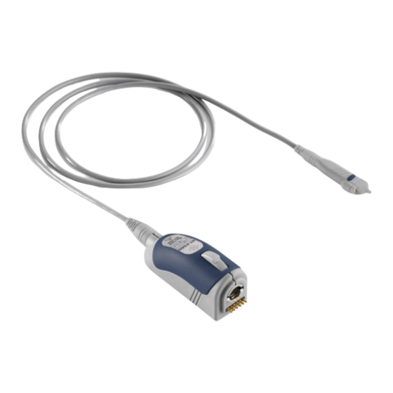
Product description Key features and key characteristics The R&S RT-ZS60 is a single-ended active voltage probe with high input impe- dance. It is used for ground-referenced voltage measurements from DC to 6 GHz. The R&S RT-ZS60 is optimized for single-ended measurements in environments characterized by 50 Ω... -
Page 10: Key Features
® Product description R&S RT-ZS60 Unpacking and checking Extremely low noise and virtually no harmonic distortions Micro button Rohde & Schwarz probe interface 2.1.2 Key features Micro button The micro button remotely controls important functions of the Rohde & Schwarz oscilloscope. -
Page 11: Description Of The Probe
4. Check the equipment for damage. If the delivery is incomplete or equipment is damaged, contact Rohde & Schwarz. Delivery notes The delivery contains the following items: ● R&S RT-ZS60 active voltage probe ● Carrying case ● Accessory boxes ●... -
Page 12: Probe Head
DUT. Different accessories for the signal and ground sockets allow the probe head to be connected to a wide range of DUTs. The signal socket of the R&S RT-ZS60 has a special design to ensure optimal performance. The signal socket is not compatible to standard accessories based on 0.64 mm (25 mil) square pins or 0.8 mm (35 mil) round pins. -
Page 13: Accessories And Items
(1) Rohde & Schwarz probe interface with 7 mm (276 mil) coaxial connector and 6 pogo pins (2) Release knob Accessories and items The figure below shows all accessories that are available for the R&S RT-ZS60 active voltage probe. User Manual 1418.7342.02 ─ 05... -
Page 14: Accessories Supplied
Figure 2-1: Available accessories 2.4.1 Accessories supplied The following table shows the accessories supplied with the R&S RT-ZS60 active voltage probe. Table 2-1: Accessories supplied Item Quantity Description Signal pin, solder in Signal pin User Manual 1418.7342.02 ─... - Page 15 ® Product description R&S RT-ZS60 Accessories and items Item Quantity Description Signal adapter, square pin Ground pin, solder in Ground pin, pogo Ground adapter, square pin Lead, 6 cm / 2.4 in Lead, 15 cm / 5.9 in Mini clip...
-
Page 16: Optional Accessories
® Product description R&S RT-ZS60 Accessories and items Item Quantity Description Micro clip Marker band kit Carrying case with foam inlay For a list of spare parts, see Chapter 5.7, "Spare parts", on page 43. 2.4.2 Optional accessories If the delivered accessories do not meet individual customer requirements, Rohde &... -
Page 17: Service Accessories
Accessories Items Quantity R&S RT‑ZA9 probe box to N / USB adapter The adapter connects the R&S RT-ZS60 active voltage probe to any other oscilloscope or any other measurement instrument (e.g. a network or spectrum analyzer). Using the USB interface of the adapter, the probe can be powered and controlled from any conventional PC. -
Page 18: Connecting The Probe
Connecting the probe to the oscilloscope Connecting the probe Handling the probe The R&S RT-ZS60 can withstand a moderate amount of physical and electrical stress. To avoid damage, treat the probe with care: ● Handle the probe by the probe head. -
Page 19: Identification Of The Probe
® Connecting the probe R&S RT-ZS60 Identification of the probe Connect the probe box (1) to the Rohde & Schwarz probe interface of the oscilloscope (2). The probe snaps in when connected properly to the port. Figure 3-1: Connecting the probe to the Rohde & Schwarz oscilloscope ►... -
Page 20: Connecting The Probe To The Dut
® Connecting the probe R&S RT-ZS60 Connecting the probe to the DUT The complete probe information is shown in the probe settings dialog. For more information, refer to the user manual of your oscilloscope. Connecting the probe to the DUT This chapter describes the different ways of connecting the probe to the DUT. - Page 21 ® Connecting the probe R&S RT-ZS60 Connecting the probe to the DUT Pins Signal pin and ground pin, pogo Using the signal pin and ground pin, manual measurements can be performed without or with only minor limitation of the measurement bandwith.
- Page 22 Connecting the probe to the DUT Signal pin, solder in, and ground pin, solder-in Using two solder-in pins for ground and signal, the R&S RT-ZS60 is soldered directly into the circuit. The pins can be exchanged on the probe and can remain in the circuit.
- Page 23 ® Connecting the probe R&S RT-ZS60 Connecting the probe to the DUT Signal adapter, square pin, and ground adapter, square pin Using two square-in pin adapters for ground and signal, the probe can be connected directly to a pin strip.
- Page 24 In addition, it allows micro and mini clips to be connected to the probe. Connencting a lead to the signal socket of the R&S RT-ZS60 requires a signal adapter, square pin. Length: Short lead: 6 mm (236 mil) Long lead: 15 mm (591 mil) User Manual 1418.7342.02 ─...
- Page 25 ® Connecting the probe R&S RT-ZS60 Connecting the probe to the DUT Clips Mini and micro clips The mini clip is designed for probing large IC pins, wires and through-hole components. The micro clip is designed for probing IC pins and thin wires in fine-pitch applications.
-
Page 26: Features And Characteristics Of Active Voltage Probes
® Features and characteristics of active voltage probes R&S RT-ZS60 Zero adjustment Features and characteristics of active voltage probes Zero adjustment The zero error can impair the measurement results, therefore, correct the zero error if necessary. The zero error of the probe itself is very small. -
Page 27: Offset Compensation
® Features and characteristics of active voltage probes R&S RT-ZS60 Offset compensation Offset compensation The offset compensation function can compensate a DC component of the input signal, even in front of the active amplifier in the probe tip. As a result, the entire dynamic range of the probe is maintained. -
Page 28: Micro Button
® Features and characteristics of active voltage probes R&S RT-ZS60 R&S ProbeMeter Micro button The micro button provides easy and quick access to important functions of the Rohde & Schwarz oscilloscope. After a function has been assigned, pressing the micro button remotely controls this specific function on the base unit. For exam- ple, "Run continuous"... -
Page 29: Measurement Principles
26. Measurement principles The R&S RT-ZS60 active voltage probe provides an electrical connection between the DUT and the oscilloscope. The probe transfers the voltage of the electrical signal tapped off the DUT to the oscilloscope, where it is displayed graphically. - Page 30 ® Features and characteristics of active voltage probes R&S RT-ZS60 Measurement principles Figure 4-2: Equivalent circuit model of the R&S RT-ZS60 probe Table 4-1: Designations Abbreviation Description Voltage at the test point without probe connected Voltage at the test point with probe connected,...
-
Page 31: Signal Integrity Of The Transferred Signal
The following explanations refer to the probe itself, but can also be applied to the entire system. Figure 4-3: Amplitude/frequency response of the R&S RT-ZS60 The bandwidth: ● Specifies the maximum frequency at which a purely sinusoidal signal is still transferred at 70 % (–3 dB) of its amplitude. - Page 32 The Figure 4-3 shows the typical amplitude/ frequency response of an R&S RT-ZS60 active voltage probe. All frequency com- ponents are transferred with the same gain so that the input signal is displayed without distortion.
- Page 33 ® Features and characteristics of active voltage probes R&S RT-ZS60 Measurement principles 4.5.1.2 Connection inductance The connection inductance L is caused by connecting the probe to the DUT. In contrast to the probe-specific bandwidth, the connection inductance mainly depends on the selected type.
- Page 34 ® Features and characteristics of active voltage probes R&S RT-ZS60 Measurement principles 4.5.1.3 Performance with different connection types Table 4-2 shows three types of connection between probe and DUT as well as the associated rise times, bandwidths, input impedances and overshoots.
- Page 35 Features and characteristics of active voltage probes R&S RT-ZS60 Measurement principles Figure 4-6: Step response of the R&S RT-ZS60 with a type 1 connection Figure 4-7: Step response of the R&S RT-ZS60 with a type 2 connection User Manual 1418.7342.02 ─ 05...
-
Page 36: Signal Loading Of The Input Signal
Features and characteristics of active voltage probes R&S RT-ZS60 Measurement principles Figure 4-8: Step response of the R&S RT-ZS60 with a type 3 connection 4.5.2 Signal loading of the input signal The previous section dealt with the transfer function and step response of the probe. - Page 37 The connection inductance L has only a minor effect on the signal loading and is therefore not considered in the following. Figure 4-9: Magnitude of the input impedance of the R&S RT-ZS60 probe as a function of frequency User Manual 1418.7342.02 ─ 05...
- Page 38 Features and characteristics of active voltage probes R&S RT-ZS60 Measurement principles Figure 4-10: Signal loading caused by the R&S RT-ZS60 probe at an effective source impedance of 25 Ω Input resistance The input resistance R determines the loading of the DUT at DC and low fre- quencies (<...
-
Page 39: Probing Philosophy
® Features and characteristics of active voltage probes R&S RT-ZS60 Measurement principles 300 Ω over the whole range, the loading of high-frequency signals in 50 Ω envi- ronments is very small. Input capacitance C and minimum input impedance |Z The input capacitance C causes the input impedance to decrease for high fre- quencies above 2 GHz. - Page 40 ® Features and characteristics of active voltage probes R&S RT-ZS60 Measurement principles Figure 4-11: Unloaded and loaded input signal and step response using the example of R&S RT-ZS60 User Manual 1418.7342.02 ─ 05...
-
Page 41: Maintenance And Service
® Maintenance and service R&S RT-ZS60 Contacting customer support Maintenance and service If service or calibration is needed, contact your Rohde & Schwarz service center. Return a defective product to the Rohde & Schwarz service center for diagnosis and exchange. -
Page 42: Returning For Servicing
Calibration interval Figure 5-1: QR code to the Rohde & Schwarz support page Returning for servicing Use the original packaging to return your R&S RT-ZS60 to your Rohde & Schwarzservice center. A list of all service centers is available on: www.services.rohde-schwarz.com If you cannot use the original packaging, consider the following: 1. -
Page 43: Storage And Transport
® Maintenance and service R&S RT-ZS60 Spare parts Storage and transport Protect the product against dust. Ensure that the environmental conditions, e.g. temperature range and climatic load, meet the values specified in the data sheet. Store the product in a shock-resistant case, e.g. in the shipping case. - Page 44 ® Maintenance and service R&S RT-ZS60 Spare parts Table 5-1: Accessory spare parts Pos. Item Description Material number Signal pin, solder in 1417.0838.00 Signal pin 1175.7651.00 Signal adapter, square pin 1175.7668.00 Ground pin, solder in 1417.0538.00 Ground pin, pogo 1175.7716.00 Ground adapter, square pin 1175.7597.00...
- Page 45 ® Maintenance and service R&S RT-ZS60 Spare parts Pos. Item Description Material number Mini clip 1416.0105.00 Micro clip 1416.0111.00 Marker band kit 1416.0205.00 Pogo pin Pogo pin connector, 6 pins 3584.6396.00 R&S RT-ZK2 R&S RT-ZK2 service kit 1410.5305.02 Table 5-2: Parts for ESD prevention Pos.
-
Page 46: Functional Check
The functional check confirms the basic operation of the R&S RT-ZS60 active voltage probe. The functional check is not suitable for verifying compliance with the probe specifications. 1. Connect the R&S RT-ZS60 probe to a Rohde & Schwarz oscilloscope as described in Chapter 3.2, "Connecting the probe to the oscilloscope",... -
Page 47: Index
® Index R&S RT-ZS60 Index Probe Connection ..........18 Accessories ..........14 Probe box ..........12 Spare parts ......... 43 Probe head ..........12 Adapter ............ 17 Probe identification ........19 AutoZero ..........26 ProbeMeter ........10, 28 Probing principles ........29 Product description ........9 Bandwidth ..........9, 31...
Need help?
Do you have a question about the RT-ZS60 and is the answer not in the manual?
Questions and answers