Table of Contents
Advertisement
Quick Links
Advertisement
Table of Contents

Subscribe to Our Youtube Channel
Related Manuals for Rohde & Schwarz RT-ZC10


Summary of Contents for Rohde & Schwarz RT-ZC10
- Page 1 ® R&S RT-ZC10 Current Probe User Manual (>9Ü82) 1409780802 Version 04...
- Page 2 Trade names are trademarks of the owners. ® 1409.7808.02 | Version 04 | R&S RT-ZC10 The following abbreviations are used in this manual: R&S ® RT-ZC10 is abbreviated as R&S RT-ZC10, and ® R&S RT-ZA13 is abbreviated as R&S RT-ZA13.
-
Page 3: Table Of Contents
® Contents R&S RT-ZC10 Contents 1 Safety and regulatory information........5 1.1 Safety instructions................5 1.2 Labels on the product................7 1.3 Warning messages in the documentation.......... 8 2 Product description...............9 2.1 Key features..................9 2.2 Unpacking and checking..............9 2.3 Description of the probe..............10 3 Connecting the probe............12... - Page 4 ® Contents R&S RT-ZC10 User Manual 1409.7808.02 ─ 04...
-
Page 5: Safety And Regulatory Information
® Safety and regulatory information R&S RT-ZC10 Safety instructions Safety and regulatory information The product documentation helps you to use the product safely and efficiently. Follow the instructions provided here and in the Chapter 1.1, "Safety instructions", on page 5. - Page 6 ® Safety and regulatory information R&S RT-ZC10 Safety instructions Reconfigure or adjust the product only as described in the product documentation or the data sheet. Any other modifications can affect safety and are not permitted. Never open the casing of the product. Only service personnel authorized by Rohde &...
-
Page 7: Labels On The Product
® Safety and regulatory information R&S RT-ZC10 Labels on the product Working with current probes When working with current probes, you can measure high-frequency currents or currents that contain high-frequency components. ● Switch off the test circuit while connecting the probe. -
Page 8: Warning Messages In The Documentation
® Safety and regulatory information R&S RT-ZC10 Warning messages in the documentation Table 1-2: Labels regarding product and environment safety Labeling in line with EN 50419 for disposal of electrical and electronic equipment after the product has come to the end of its service life. -
Page 9: Product Description
Unpacking and checking Product description The R&S RT-ZC10 is an AC/DC current probe. It allows the user to make current measurements from DC to 10 MHz. By clamping on the conductor to be mea- sured, the current waveform is captured easily without interrupting the electric cir- cuit. -
Page 10: Description Of The Probe
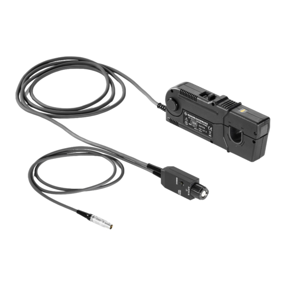
® Product description R&S RT-ZC10 Description of the probe Delivery notes The delivery contains the following items: ● User manual ● Carrying case ● R&S RT-Zxx high-voltage and current probes data sheet ● Safety instructions for oscilloscopes and accessories (multilingual) ●... - Page 11 ® Product description R&S RT-ZC10 Description of the probe 7 = Demagnetizing switch (DEMAG) 8 = Zero adjustment dial (ZERO ADJ) 9 = Output connector 10 = Power plug 11 = Terminator 12 = Power supply cable 13 = Sensor cable...
-
Page 12: Connecting The Probe
Handling the probe Connecting the probe Handling the probe The R&S RT-ZC10 can withstand a moderate amount of physical and electrical stress. To avoid damage, treat the probe with care: ● Prevent the probe from receiving mechanical shock. ● Avoid strain on the probe cable and route it carefully. Keep the cable away from heat sources, as bare conductors could be exposed if the insulation melts. -
Page 13: Connecting The Probe To The Power Supply
Turn off the power switch at the rear of the R&S RT-ZA13 probe power supply. 3. Connect the power cord. 4. Connect the power plug of the R&S RT-ZC10 to the power receptacle of the R&S RT-ZA13 probe power supply. -
Page 14: Connecting The Probe To The Oscilloscope
BNC connectors, make sure the polarity is correct. To connect the probe: 1. Insert the output connector of the R&S RT-ZC10 into one of the BNC input connectors of the oscilloscope. 2. Turn the collar until it clicks. -
Page 15: Setting Up And Demagnetizing
Setting up and demagnetizing 1. With the waveform measuring instrument input at ground, adjust the waveform to the zero position. 2. Connect the R&S RT-ZC10 current probe to the power supply as described in Chapter 3.2, "Connecting the probe to the power supply", on page 13. -
Page 16: Connecting The Probe To The Dut
® Connecting the probe R&S RT-ZC10 Connecting the probe to the DUT The demagnetizing process takes about 3 seconds. During demagnetizing, a demagnetizing waveform is shown on the oscilloscope. The positive and neg- ative components of this waveform may be asymmetrical. -
Page 17: Considerations For Measurements
® Connecting the probe R&S RT-ZC10 Considerations for measurements The current consumption of clamp-on probes depends on the current to be mea- sured. Confirm that the total current consumption of the probes does not exceed the rated output current of the R&S RT-ZA13 probe power supply. - Page 18 ® Connecting the probe R&S RT-ZC10 Considerations for measurements Self-heating may happen if the ambient temperature increases or the mea- surement current waveform contains other frequency components. ● If the input current exceeds a certain level, generated heat activates a built-in safety function that blocks normal output.
- Page 19 ® Connecting the probe R&S RT-ZC10 Considerations for measurements Drift, oscillation, and sound ● Immediately after powering on, the probe may be subject to an appreciable offset drift due to the effect of self-heating. Therefore, warm up the probe for about 30 minutes before carrying out measurements.
- Page 20 ® Connecting the probe R&S RT-ZC10 Considerations for measurements At high frequencies, common mode noise may affect measurements taken on the high-voltage side of circuits. If this occurs, reduce the frequency range of the waveform measuring instrument, or clamp onto the low-voltage side of the circuit, as appropriate.
-
Page 21: Maintenance And Service
® Maintenance and service R&S RT-ZC10 Contacting customer support Maintenance and service If service or calibration is needed, contact your Rohde & Schwarz service center. Return a defective product to the Rohde & Schwarz service center for diagnosis and exchange. -
Page 22: Returning For Servicing
Calibration interval Figure 4-1: QR code to the Rohde & Schwarz support page Returning for servicing Use the original packaging to return your R&S RT-ZC10 to your Rohde & Schwarzservice center. A list of all service centers is available on: www.services.rohde-schwarz.com If you cannot use the original packaging, consider the following: 1. -
Page 23: Storage And Transport
® Maintenance and service R&S RT-ZC10 Disposal Storage and transport Protect the product against dust. Ensure that the environmental conditions, e.g. temperature range and climatic load, meet the values specified in the data sheet. Store the product in a shock-resistant case, e.g. in the shipping case. -
Page 24: S Rt-Za13 Probe Power Supply
® R&S RT-ZA13 probe power supply R&S RT-ZC10 R&S RT-ZA13 probe power supply This unit is a special-purpose power supply for the current probes. You can connect up to four current probes to the power supply. Front view Rear view...
Need help?
Do you have a question about the RT-ZC10 and is the answer not in the manual?
Questions and answers