Table of Contents
Advertisement
Quick Links
Advertisement
Table of Contents

Related Manuals for Rohde & Schwarz R&S RT-ZPR20


Summary of Contents for Rohde & Schwarz R&S RT-ZPR20
- Page 1 ® R&S RT-ZPR20 ® R&S RT-ZPR40 Power-Rail Probe User Manual (B0ÀS2) 1800503502...
- Page 2 ® This manual describes the following R&S RT-ZPR models: ● R&S ® RT-ZPR20 (1800.5006.02) ● R&S ® RT-ZPR40 (1800.5406.02) © 2019 Rohde & Schwarz GmbH & Co. KG Mühldorfstr. 15, 81671 München, Germany Phone: +49 89 41 29 - 0 Fax: +49 89 41 29 12 164 Email: info@rohde-schwarz.com...
-
Page 3: Table Of Contents
® ® Contents R&S RT-ZPR20 R&S RT-ZPR40 Contents 1 Safety Information..............5 2 Product Description.............. 7 2.1 Key Features and Key Characteristics..........7 2.2 Unpacking....................8 2.2.1 Inspecting the Contents................8 2.3 Description of the Probe..............9 2.3.1 Probe Box....................9 2.3.2 Supplied Accessories................10 2.3.3 Optional Accessories................11 2.3.4 Service Accessories................12... - Page 4 ® ® Contents R&S RT-ZPR20 R&S RT-ZPR40 6 Maintenance and Service............28 6.1 Cleaning....................28 6.2 Contacting Customer Support............28 6.3 Returning for Servicing..............29 6.4 Calibration Interval................30 6.5 Discarding the Product..............30 6.6 Spare Parts..................30 User Manual 1800.5035.02 ─ 03...
-
Page 5: Safety Information
® ® Safety Information R&S RT-ZPR20 R&S RT-ZPR40 Safety Information The product documentation helps you use the R&S RT-ZPR20/40 safely and effi- ciently. Follow the instructions provided here and in the "Safety Instructions". Keep the product documentation nearby and offer it to other users. Intended use The R&S RT-ZPR20/40 is intended for the development, production and verifica- tion of electronic components and devices in industrial, administrative, and labo-... - Page 6 ® ® Safety Information R&S RT-ZPR20 R&S RT-ZPR40 The R&S RT-ZPR20/40 can withstand a moderate amount of physical and electri- cal stress. To avoid damage, treat the probe with care: ● Always observe the specified input voltage limits and measurement ranges. ●...
-
Page 7: Product Description
® ® Product Description R&S RT-ZPR20 R&S RT-ZPR40 Key Features and Key Characteristics Product Description Key Features and Key Characteristics The R&S RT-ZPR20/40 power-rail probe is designed for power integrity measure- ments. The R&S RT-ZPR20/40 is specifically built to measure small signals in the millivolt range with very large DC-offset components up to ±60 V. -
Page 8: Unpacking
® ® Product Description R&S RT-ZPR20 R&S RT-ZPR40 Unpacking Unpacking The carrying case contains the following items: ● R&S RT-ZPR20/40 power-rail probe ● Accessory container ● Pigtail cables ● User manual ● R&S RT-ZPR20/40 data sheet ● Calibration certificate ● R&S RT-ZA25 power rail browser kit ●... -
Page 9: Description Of The Probe
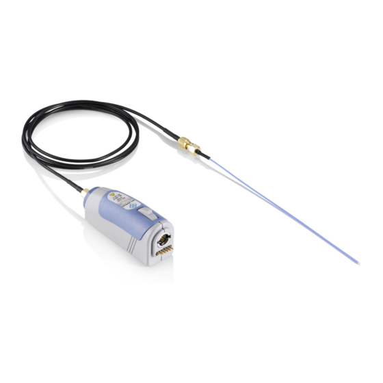
® ® Product Description R&S RT-ZPR20 R&S RT-ZPR40 Description of the Probe Description of the Probe The probe consists of the active probe box with an Rohde & Schwarz probe inter- face to connect to the oscilloscope, and an SMA connector to connect to the DUT. Use the SMA interface to connect the supplied solder-in and extension cables or the power rail browser. -
Page 10: Supplied Accessories
® ® Product Description R&S RT-ZPR20 R&S RT-ZPR40 Description of the Probe 2.3.2 Supplied Accessories Before you can use the probe for measurements, connect one of the accessories to the SMA connector at the probe box. Table 2-1 shows the accessories that are supplied with the R&S RT-ZPR20/40 power-rail probe. -
Page 11: Optional Accessories
® ® Product Description R&S RT-ZPR20 R&S RT-ZPR40 Description of the Probe Item Quantity Description Solder wire, lead free, 5 m Adhesive pads For a list of spare parts, see Chapter 6.6, "Spare Parts", on page 30. 2.3.3 Optional Accessories If the delivered accessories do not meet individual customer requirements, Rohde &... -
Page 12: Service Accessories
® ® Product Description R&S RT-ZPR20 R&S RT-ZPR40 Description of the Probe Item Description R&S RT-ZA10 SMA adapter SMA adapter with SMA (female) jack to BNC (male) plug. R&S RT-ZAP probe positioner Use the R&S RT-ZAP probe positioner to position and stabilize your probe. - Page 13 ® ® Product Description R&S RT-ZPR20 R&S RT-ZPR40 Description of the Probe Table 2-3: Service accessories Item Description R&S RT-ZK1 The service kit is used to calibrate the probe, to do perform- ance tests, and for servicing. The service kit includes all adapters and accessories to connect the probe to the required measuring instruments.
-
Page 14: Putting Into Operation
® ® Putting into Operation R&S RT-ZPR20 R&S RT-ZPR40 Connecting the Probe to the Oscilloscope Putting into Operation The probe is designed for usage with oscilloscopes that have a Rohde & Schwarz probe interface. Supported Rohde & Schwarz oscilloscopes are listed in the pro- be's data sheet. -
Page 15: Identification Of The Probe
® ® Putting into Operation R&S RT-ZPR20 R&S RT-ZPR40 Identification of the Probe Figure 3-1: Connecting the probe to the Rohde & Schwarz oscilloscope Disconnecting 1. Disconnect the accessories from the probe box before changing a probing point, or before disconnecting the probe box from the oscilloscope. 2. -
Page 16: Offset Compensation And Dynamic Range
® ® Putting into Operation R&S RT-ZPR20 R&S RT-ZPR40 Offset Compensation and Dynamic Range The oscilloscope settings for attenuation and offset are automatically adjusted. After the probe is connected to the oscilloscope and the settings are adjusted, the waveform is shown for the channel to which the probe is connected. The complete probe information is shown in the probe settings dialog. -
Page 17: Ac Coupling Mode
® ® Putting into Operation R&S RT-ZPR20 R&S RT-ZPR40 AC Coupling Mode Figure 3-2: Offset compensation voltage and dynamic range AC Coupling Mode The R&S RT-ZPR20/40 power-rail probe features an internal AC coupling mode with a low frequency cutoff at 10 Hz to block DC components of the input signal. The AC coupling is set inside the probe, the full bandwidth of the probe remains. -
Page 18: R&S Probemeter
® ® Putting into Operation R&S RT-ZPR20 R&S RT-ZPR40 R&S ProbeMeter R&S ProbeMeter The R&S ProbeMeter is an integrated voltmeter that measures DC voltages with higher precision compared to the oscilloscope's DC accuracy. The DC measure- ment is performed continuously and in parallel to the time domain measurement of the oscilloscope. -
Page 19: Connecting The Probe To The Dut
® ® Connecting the Probe to the DUT R&S RT-ZPR20 R&S RT-ZPR40 R&S RT-ZA25 Power Rail Browser Kit Connecting the Probe to the DUT This chapter describes how to connect the probe to the DUT using different accessories supplied for the R&S RT-ZPR20/40 probe. The various accessories are described and their use is explained. - Page 20 ® ® Connecting the Probe to the DUT R&S RT-ZPR20 R&S RT-ZPR40 R&S RT-ZA25 Power Rail Browser Kit Risk of injuries Always observe the maximum rating of ±60 V DC, 30 V AC (RMS), or ±42 V AC (peak). The R&S RT-ZA25 is not equipped with a protective impedance and must not be used to measure higher voltages.
-
Page 21: R&S Rt-Za26 Pigtail Cable
® ® Connecting the Probe to the DUT R&S RT-ZPR20 R&S RT-ZPR40 R&S RT-ZA26 Pigtail Cable For convenient probing and medium band- width, use the flexible ground lead with adapter. Use the long-distance ground lead with alliga- tor clip to contact far away ground points. Due to the larger loop inductance, bandwidth is decreased. - Page 22 ® ® Connecting the Probe to the DUT R&S RT-ZPR20 R&S RT-ZPR40 R&S RT-ZA26 Pigtail Cable The R&S RT-ZA26 pigtail cable is well suited for creating solid contact with test points that are hard to reach (e.g. IC pins, SMT parts). Bandwidth: •...
-
Page 23: Sma Extension Cable
® ® Connecting the Probe to the DUT R&S RT-ZPR20 R&S RT-ZPR40 SMA Extension Cable Risk of damaging the probe due to excess heat When using the R&S RT-ZA26 pigtail cable, do not expose the R&S RT- ZPR20/40 probe box to temperatures outside the valid range (see "Observe operating temperature range"... -
Page 24: Measurement Principles
® ® Measurement Principles R&S RT-ZPR20 R&S RT-ZPR40 Measurement Principles The R&S RT-ZPR20/40 power-rail probe provides an electrical connection between the DUT and the oscilloscope. The probe transfers the voltage of the electrical signal tapped off the DUT to the oscilloscope, where it is displayed graphically. -
Page 25: Step Response
® ® Measurement Principles R&S RT-ZPR20 R&S RT-ZPR40 Step Response Abbreviation Description Voltage at the test point without probe connected Voltage at the test point with probe connected, corresponds to the input volt- age of the probe Source impedance of the DUT DC input resistance of the probe RF input resistance Coupling capacitance... -
Page 26: Frequency Response
® ® Measurement Principles R&S RT-ZPR20 R&S RT-ZPR40 Frequency Response Frequency Response The R&S RT-ZPR20/40 probe is a dedicated power rail probe, designed for mea- surements at low impedance voltage sources such as DC power supplies with an output impedance < 1 Ohm. A DUT with an output impedance (R ) higher than 1 Ohm leads to a mismatch between DC gain and AC gain. -
Page 27: Input Impedance
® ® Measurement Principles R&S RT-ZPR20 R&S RT-ZPR40 Input Impedance Input Impedance The input signal loading caused by the probe is determined by its input impe- dance Z Figure 5-1 illustrates an equivalent circuit model. The resulting input impedance versus frequency is indicated in Figure 5-4. -
Page 28: Maintenance And Service
® ® Maintenance and Service R&S RT-ZPR20 R&S RT-ZPR40 Contacting Customer Support Maintenance and Service Like all Rohde & Schwarz products, Rohde & Schwarz probes and adapters are of high quality and require only minimum service and repair. However, if service or calibration is needed, contact your Rohde &... -
Page 29: Returning For Servicing
® ® Maintenance and Service R&S RT-ZPR20 R&S RT-ZPR40 Returning for Servicing Europe, Africa, Middle East Phone +49 89 4129 12345 customersupport@rohde-schwarz.com North America Phone 1-888-TEST-RSA (1-888-837-8772) customer.support@rsa.rohde-schwarz.com Latin America Phone +1-410-910-7988 customersupport.la@rohde-schwarz.com Asia/Pacific Phone +65 65 13 04 88 customersupport.asia@rohde-schwarz.com China Phone +86-800-810-8228 / +86-400-650-5896... -
Page 30: Calibration Interval
® ® Maintenance and Service R&S RT-ZPR20 R&S RT-ZPR40 Spare Parts 4. Seal the box with tape. 5. Address the package to your nearest Rohde & Schwarz service center. Calibration Interval The recommended calibration interval for R&S RT-ZPR20/40 power-rail probe is two years. - Page 31 ® ® Maintenance and Service R&S RT-ZPR20 R&S RT-ZPR40 Spare Parts Item Description Part Number SMA extension cable, 1 m 1800.5241.00 For R&S RT-ZPR20 SMA extension cable low loss, 1 1337.9081.00 For R&S RT-ZPR40 Spare parts for the R&S RT-ZA25 power rail browser kit Ground lead with alligator clip 1800.5335.00 Dual adapter...
- Page 32 ® ® Maintenance and Service R&S RT-ZPR20 R&S RT-ZPR40 Spare Parts Table 6-2: Parts for ESD prevention Pos. Item Material number ESD wrist strap 0008.9959.00 ESD grounding cable 1043.4962.00 User Manual 1800.5035.02 ─ 03...
Need help?
Do you have a question about the R&S RT-ZPR20 and is the answer not in the manual?
Questions and answers