FAAC DAAB EP104 Quick Start Manual
Hide thumbs
Also See for DAAB EP104:
- Instruction manual (74 pages) ,
- Installation manual (60 pages) ,
- Quick manual (4 pages)
Table of Contents
Advertisement
Quick Links
Advertisement
Table of Contents

Related Manuals for FAAC DAAB EP104


Summary of Contents for FAAC DAAB EP104
- Page 1 DAAB EP104 Quick Start Guide...
-
Page 2: Table Of Contents
Risk Assessment undertaken by the installer. The installer should still familiarise themselves with the full manual and the safety information contained within. (available https://www.faac.se/data/pdf/instruction_m anual_ep104_4_08_r4_en_with_sheet_c999 .pdf Page | 1... -
Page 3: Installation Sequence
Wireless Safety Edges can be connected via the same terminals as in “13-a” but the output of the Wireless Safety Edge system should be configured to output a resistive circuit the BUS 2easy connection if using the FAAC XTR and XTS Wireless Receiver system c. -
Page 4: Ep104 Basic Power, Motor And Encoder Wiring
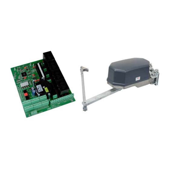
EP104 Basic Power, Motor and Encoder Wiring Ensure that the EP104-1 or EP104-2 is in a suitable enclosure and ideally be in visual sight of the gate for commissioning purposes. Fit the Gate Operator/s as per the drawings provided. Power and Motor Connections Connect the main power to the board and wire the motors in accordance to the power available on site and matching motor. -
Page 5: Encoder, Stop And Photocell Connections
Encoder, Stop and Photocell Connections Encoders Connect the Encoders to the EP104 Board as shown below. Please ensure that the cable supplying the encoder is shielded or not sharing the conduit as the motor power supply. Stop Circuit Link Terminal 7 to 12 if no emergency stop button is present, otherwise fit a N/C Emergency Stop Button across the terminals. -
Page 6: Configuring The Ep104
Configuring the EP104 Before starting programming of the EP104, it is best to familiarize yourself with navigating through the menus. The EP104 display can show a value up to 4 digits long, or a channel number with the prefix C, d, F, L, o, P, or r followed by 3 digits. -
Page 7: Ep104 - First Steps
EP104 – First Steps Step 1 First navigate to C999 and change the value to “0” (this allows display of all registers). Ensure that Photo/Safe/Stop/24V are all illuminated Green. To check motor rotation and encoders, we first put the EP104 into Service Mode. In this mode only the internal Open/Stop/Close buttons are functional. It should come default in this mode. -
Page 8: Step 5 - Safety Edge Circuit
16. C231 (Motor Power Readout), it should say 0.00 with the gate stopped. Press and hold the Open Button on the board and make a note of the value when the gate is moving and then press the Close Button on the board and make a note of the value when gate is moving 17. -
Page 9: Ep104 - Inputs And Automatic Closing
EP104 – Inputs and Automatic Closing Inputs The EP104-1 has 6 different inputs, as shown below. Partial Openings If only 1 gate is required to open in a double gate system from time to time, we would normally suggest using Input 3. -
Page 10: Ep104 - Outputs And Connecting A Lock
EP104 – Outputs and Connecting a Lock Outputs The EP104 does not have any outputs natively. If an output is required to control traffic lights, control locks or provide position indicators to a BMS on site, then the use of a DB407 Output Card is required. Please note that if you are replacing a version 4.06 or below EP104, you will also require a new DB407 as the current control boards are not compatible with the older versions of the DB401 (the original version of the output card). -
Page 11: Wiring A Traffic Light To A Ep104
Wiring a Traffic Light to a EP104 When it is being used to connect a Traffic Light, we would recommend the use of o5 and o6 and i3 and run a separate power supply positive to the Traffic Light and you would switch the negative through the outputs as per below. -
Page 12: Common Errors And Troubleshooting
Common Errors and Troubleshooting Troubleshooting Page | 11...
Need help?
Do you have a question about the DAAB EP104 and is the answer not in the manual?
Questions and answers