Table of Contents
Advertisement
Advertisement
Table of Contents

Subscribe to Our Youtube Channel
Summary of Contents for FAAC 746ER
- Page 1 746ER & 780D 746ER & 780D...
-
Page 2: Ec Declaration Of Conformity For Machines
17) Use of at least one indicator-light (e.g. FAACLIGHT ) is recommended 6) FAAC declines all liability caused by improper use or use other than that for every system, as well as a warning sign adequately secured to the for which the automated system was intended. -
Page 3: Product View
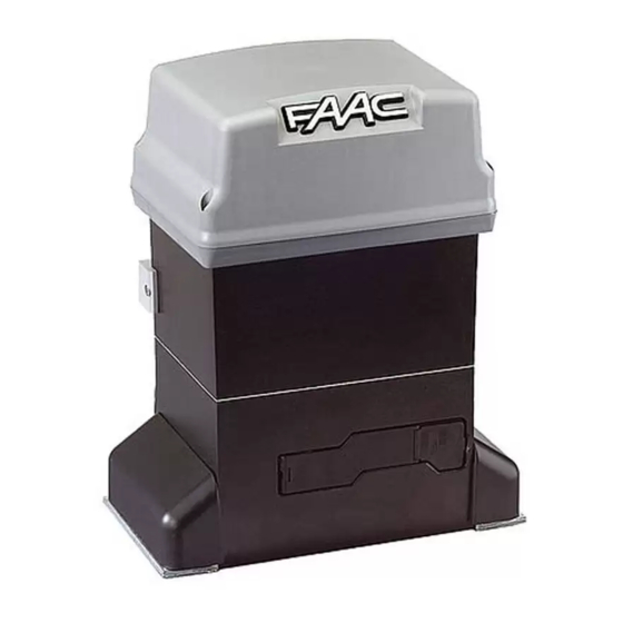
746 ER Z16 - 746 ER Z20 - 746 ER CAT - 746 ER RF Ta = opening time The FAAC mod. 746 automated system for sliding gates is an Tc = closing time electro-mechanical operator transmitting motion to the sliding leaf Tp = pause time via a rack or chain pinion appropriately coupled to the gate. -
Page 4: Dimensions
To make the connections efficiently, allow the cables to 2. DIMENSIONS project by about 40 cm from the hole (Figs.5-6 ref.³) of the foundation plate. Fig. 4 Fig. 2 3. ELECTRIC EQUIPMENT (standard system) ³ Fig. 5 Operator 746 with 780D equipment Photocells Key-operated push-button Flashing lamp... - Page 5 5) Secure the gearmotor to the foundation plate, tightening the nuts as in Fig.12. 6) Prepare the operator for manual operating mode as described in chapter 8. Fig. 12 Fig. 8 4.4. INSTALLING THE RACK 4.4.1. STEEL RACK TO WELD (Fig.13) 1) Place the three threaded pawls on the rack element, positioning them at the top of the slot.
- Page 6 Fig. 19 4.5.2. MOD. 746 ER RF (Figs. 20 - 21) Fig. 15 1) Insert the spring pin on the shaft, using a hammer. 2) Fit the idle transmissions bracket on the gearmotor flange, using the four screws (M5 x 12) and the appropriate washers , in the kit as shown in Fig.
-
Page 7: Components
5.3. LAYOUT AND COMPONENTS 5. CONTROL BOARD 780D SIGNALLING AND PROGRAMMING DISPLAY 5.1. WARNINGS Led INPUTS STATUS CONTROL LED Important: Before attempting any work on the control board (connections, maintenance), always turn off power. LOW VOLTAGE TERMINAL BOARD - Install, upstream of the system, a differential thermal breaker with CONNECTOR FOR DECODER/MINIDEC/RP RECEIVER adequate tripping threshold. -
Page 8: Electric Connections
Opening safety devices: they are tripped when an obstacle is 5.4. ELECTRIC CONNECTIONS detected only during gate opening movement. They cause immediate closure and resumption of opening motion on release (see programming in par. 5.5.2.) 230Vac 50-60Hz Closing safety devices: they are tripped when an obstacle is detected only during gate closing movement. - Page 9 Connection of two pairs of closing photocells and two Connection of a pair of opening photocells edge safety devices Fig. 29 Connection of a pair of closing photocells Fig. 32 Connection of a pair of closing photocells, a pair of opening photocells and a pair of opening/closing photocells Fig.
- Page 10 To install several partial opening pulse generators, connect Connection of a pair of closing photocells and a pair of the N.O. contacts in parallel (fig.35). opening/closing photocells FSW OP - Opening safety devices contact (terminal 3): The purpose of the opening safety devices is to protect the leaf movement area during opening.
- Page 11 TX -FSW - Negative for power supply to photocell transmitters 5.5. PROGRAMMING (terminal 11) To program operation of the automated system, access the If you use this terminal for connecting the negative for "PROGRAMMING" mode with keys F,+ and -, and using the display supplying power to the photocell transmitters, you may, if on the equipment.
- Page 12 Display Function Default Display Function Default FORCE: FAIL SAFE: Adjusts Motor thrust. If this function is activated, it enables a function test of the photocells before any gate = minimum force movement. If the test fails (photocells not = maximum force serviceable signalled by value on the display), the gate does not start moving.
- Page 13 Display Function Default Display Function Default OPENING PHOTOCELLS LOGIC: PARTIAL OPENING: Select the tripping mode of the opening You can adjust the width of partial leaf photocells. opening. They operate for the opening movement Time can be adjusted from only: they stop the movement and restart it 1 second steps.
- Page 14 Attention: due to the powerful magnetic fields the supplied 6. START-UP magnets produce, the magnets can damage magnetic band 6.1. ELECTRIC CONNECTIONS components (credit cards, magnetic tapes, floppy disks, etc) and electronic and mechanical equipment (e.g. watches, LCD Make all electrical connections to the board as in chapter 5, screens).
- Page 15 Notes on plate positioning To reduce torque, turn the screw anti-clockwise. Ü The operator is supplied with the clutch set to maximum level. • To ensure correct operation, allow at least 2 cm from the Therefore, you must initially turn the screw anti-clockwise to mechanical stop limit in the gate stop position.
- Page 16 CN 60E control unit to it (Fig. 50). For connection and operation, refer to the specific instructions. 11.SPECIAL APPLICATIONS Fig. 52 There are no special applications. 13.REPAIRS For any repairs, contact the FAAC authorised Repair Centres.
- Page 19 - Do not attempt any kind of repair of direct action whatsoever and contact FAAC qualified personnel only. - Call in qualified personnel at least every 6 months to check the efficiency of the automated system, safety devices and earth connection.


Need help?
Do you have a question about the 746ER and is the answer not in the manual?
Questions and answers