Table of Contents
Advertisement
Quick Links
Advertisement
Table of Contents

Related Manuals for DFI KD331-C236/Q170


Summary of Contents for DFI KD331-C236/Q170
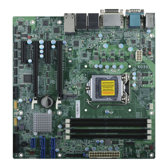
- Page 1 KD331-C236/Q170 MicroATX Industrial Motherboard User’s Manual A-467-M-2003...
-
Page 2: Copyright
Copyright FCC and DOC Statement on Class B This publication contains information that is protected by copyright. No part of it may be re- This equipment has been tested and found to comply with the limits for a Class B digital produced in any form or by any means or used to make any transformation/adaptation without device, pursuant to Part 15 of the FCC rules. -
Page 3: Table Of Contents
Table of Contents RJ45 LAN Ports ������������������������������������������������������������������������������������������� 22 USB Ports ��������������������������������������������������������������������������������������������������� 22 Audio ��������������������������������������������������������������������������������������������������������� 23 I/O Connectors ������������������������������������������������������������������������������������������� 24 SATA (Serial ATA) Connectors ���������������������������������������������������������������������� 24 Copyright �������������������������������������������������������������������������������������������������������������2 Digital I/O Connector ���������������������������������������������������������������������������������� 24 Cooling Fan Connectors������������������������������������������������������������������������������� 25 Trademarks ��������������������������������������������������������������������������������������������������������2 Power Connectors ��������������������������������������������������������������������������������������� 25 Chassis Intrusion Connector ������������������������������������������������������������������������... -
Page 4: Warranty
Warranty Static Electricity Precautions 1. Warranty does not cover damages or failures that arised from misuse of the product, It is quite easy to inadvertently damage your PC, system board, components or devices even inability to use the product, unauthorized replacement or alteration of components and before installing them in your system unit. -
Page 5: About The Package
The package contains the following items. If any of these items are missing or damaged, please contact your dealer or sales representative for assistance. • One KD331-C236/Q170 motherboard • One COM port cable (Length: 300mm, 2 x COM ports) •... -
Page 6: Chapter 1 - Introduction
Chapter 1 - Introduction Specifications SYSTEM Processor KD331-C236: INTERNAL I/O Serial 1 x RS-232/422/485 (RS-232 with power) (2.54mm pitch) ® ® Intel Xeon E3 v5/v6 LGA 1151 Socket Processors with TDP up to 80W with C236 SKU 4 x RS-232 (2.54mm pitch) 6th/7th Generation Intel ®... -
Page 7: Features
Features • Wake-On-LAN • Watchdog Timer This feature allows the network to remotely wake up a Soft Power Down (Soft-Off) PC. It is supported via the onboard LAN port or via a PCI LAN card that uses the PCI PME (Power Man- agement Event) signal. - Page 8 • Power Failure Recovery When power returns after an AC power failure, you may choose to either power-on the system manually or let the system power-on automatically. • USB The system board supports the new USB 3.0. It is capable of running at a maximum transmis- sion speed of up to 5 Gbit/s (625 MB/s) and is faster than USB 2.0 (480 Mbit/s, or 60 MB/s) and USB 1.1 (12Mb/s).
-
Page 9: Chapter 2 - Hardware Installation
COM 2 RS232/422/485 Select (JP12) Vertical USB COM 2 RS232/422/485 Select (JP13) • Four 288-pin ECC DIMM up to 64GB (KD331-C236) USB 2.0 Four 288-pin DIMM up to 64GB (KD331-Q170) • Dual Channel DDR4 2133/2400 MHz Chapter 2 Hardware Installation www.dfi.com... -
Page 10: Installing The Dimm Module
Chapter 2 The system board supports the following memory interface. Installing the DIMM Module Single Channel (SC) Note: The system board used in the following illustrations may not resemble the actual Data will be accessed in chunks of 64 bits (8B) from the memory channels. board. -
Page 11: Cpu
Chapter 2 6. Grasping the module by its edges, position the module above the socket with the “notch” in the module aligned with the “key” on the socket. The keying mechanism ensures the module can be plugged into the socket in only one way. The system board is equipped with a surface mount LGA 1151 socket. -
Page 12: Installing The Cpu
Chapter 2 Load lever Installing the CPU 5. Lifting the load lever will at the same time lift the load plate. 1. Make sure the PC and all other peripheral devices connected to it has been powered down. Lift the load lever up to 2. - Page 13 Chapter 2 7. Insert the CPU into the 8. Close the load plate then socket. The gold triangular push the load lever down. mark on the CPU must align with the corner of While closing the load Retention knob the CPU socket shown on plate, make sure the front the photo.
-
Page 14: Installing The Fan And Heat Sink
Chapter 2 Installing the Fan and Heat Sink 4. Rotate each screw that are diagonally across the heat sink. Perform the same The CPU must be kept cool by using a CPU fan with heat sink. Without sufficient air circula- procedure for the other tion across the CPU and heat sink, the CPU will overheat damaging both the CPU and system screws. -
Page 15: Block Diagram
Chapter 2 Block Diagram Channel A Channel A 2133/2400MHz 2133/2400MHz R.G.B R.G.B PTN3355 PTN3355 DDR4 DIMM 2x DDR4 DIMM 2x Channel B Channel B 2133/2400MHz 2133/2400MHz Core i7/i5/i3 Core i7/i5/i3 DDR4 DIMM 2x DDR4 DIMM 2x DVI-D DVI-D PCIe x16 PCIe x16 PCIe x16 slot 2x PCIe x16 slot 2x... -
Page 16: Mechanical Drawing
Chapter 2 Mechanical Drawing Jumper Settings Clear CMOS Data 209.55 203.20 198.98 173.73 165.82 1-2 On: Normal (default) 135.39 105.13 2-3 On: Clear CMOS Data 90.81 84.63 If you encounter the followings, a) CMOS data becomes corrupted. b) You forgot the supervisor or user password. 47.29 you can reconfigure the system with the default values stored in the ROM BIOS. -
Page 17: Com1/Com2 Rs232/422/485 Select
Chapter 2 COM1/COM2 RS232/422/485 Select JP7 (COM1)/JP11 (COM2) 2 4 6 2 4 6 2 4 6 1 3 5 1 3 5 1 3 5 JP7 (COM 1) 1-2 On: 3-4 On: 5-6 On: RS232 (default) RS422 Full Duplex RS485 JP8/JP10 (COM 1) JP10... -
Page 18: Com1/Com2 Rs232/Power Select
RS232 with power JP14 (COM 2) USB 5/6 (USB 2.0) JP39 USB 7/8/9/10 (USB 2.0) JP40 USB 5/6 (USB 3.0) JP41 1-3 (RI-), 2-4 (DCD-) On: 3-5 (+5V), 4-6 (+12V) On: RS232 (default) RS232 with power Chapter 2 Hardware Installation www.dfi.com... -
Page 19: Rear Panel I/O Ports
Chapter 2 Rear Panel I/O Ports PS/2 Keyboard/Mouse Port PS/2 Keyboard/Mouse DVI-I COM 1 (DVI-D signal) LAN 1 LAN 2 PS/2 KB/MS LAN 4 USB 2.0 LAN 3 DP++ USB 3.0 The rear panel I/O ports consist of the following: •... -
Page 20: Com (Serial) Ports
Chapter 2 COM (Serial) Ports COM 3 to COM 6 COM 1 Pin Assignment DCD- COM 1: RS232/422/485 DTR- COM 2: DSR- RS232/422/485 RTS- CTS- COM 3/4/5/6: RS232 The pin functions of COM 1 port will vary according to setting of JP7, JP8, JP9 and JP10. Refer to “COM1/COM2 RS232/422/485 Select”... -
Page 21: Graphics Interfaces
Chapter 2 Graphics Interfaces Driver Installation The display ports consist of the following: Install the graphics driver. Refer to the chapter 4 for more information. • 1 VGA port • 1 DVI-I (DVI-D signal) port • 1 DP++ port DVI-I (DVI-D signal) DP++ VGA Port The VGA port is used for connecting a VGA monitor. -
Page 22: Rj45 Lan Ports
Chapter 2 RJ45 LAN Ports USB Ports USB 6 USB 5 USB 2.0 LAN 1 LAN 2 LAN 1 LAN 4 LAN 3 LAN 2 USB 4 USB 2 USB 1 USB 3 LAN 3-4 USB 3.0 USB 5-6 USB 3.0 USB 9-10 or Features optional vertical USB... -
Page 23: Audio
Chapter 2 Audio Driver Installation You may need to install the proper drivers in your system operation to use the USB device. Refer to your operating system’s manual or documentation for more information. Wake-On-USB Keyboard/Mouse The Wake-On-USB Keyboard/Mouse function allows you to use a USB keyboard or USB mouse to wake up a system from the S3 (STR - Suspend To RAM) state. -
Page 24: I/O Connectors
Chapter 2 I/O Connectors Digital I/O Connector SATA (Serial ATA) Connectors SATA 3.0 6Gb/s SATA 0 SATA 1 SATA 2 SATA 3 SATA 4 Digital I/O Features The 8-bit Digital I/O connector provides powering-on function to external devices that are connected to these connectors. -
Page 25: Cooling Fan Connectors
Chapter 2 Cooling Fan Connectors Power Connectors CPU Fan Ground +12V Speed CTRL Power +12V +12V System Fan 2 12 24 Power +3.3V +12V +12V +5VSB PWR_OK PS_ON# System Fan 1 +3.3V -12V +3.3V +3.3V Power Sense Use a power supply that complies with the ATX12V Power Supply Design Guide Version 1.1. These fan connectors are used to connect cooling fans. -
Page 26: Chassis Intrusion Connector
Chapter 2 Chassis Intrusion Connector Front Panel Connector Front Panel PWR-LED HD-LED RESET ATX-SW Ground Chassis Signal Intrusion HD-LED - Hard Drive LED This LED will light when the hard drive is being accessed. RESET - Reset Switch The board supports the chassis intrusion detection function. Connect the chassis intrusion sensor cable from the chassis to this connector. -
Page 27: Lan Led Connector
Chapter 2 LAN LED Connector S/PDIF Connector LAN LED SPDIF out Ground SPDIF in S/PDIF The LAN LED connector is used to detect the connection state of RJ45 LAN ports when the The S/PDIF connector is used to connect an external S/PDIF port. Your S/PDIF port may be connection is made to an active network via a cable. -
Page 28: Smbus Connector
Chapter 2 SMBus Connector Standby Power LED Standby Power LED SMBus The SMBus (System Management Bus) connector is used to connect SMBus devices. It is a multiple device bus that allows multiple chips to connect to the same bus and enable each one to act as a master by initiating data transfer. -
Page 29: Lpc Connector
Connecting the EXT-RS232/RS485 Card to the Motherboard With DFI’s proprietary technology, KD331-C236/Q170 supports two extension modules for ad- ditional four COM ports. The EXT-RS232/RS485 card is connected to KD331-C236/Q170 via the LPC connector. The illustrations below guide you how to connect the extension module to the motherboard. -
Page 30: Expansion Slots
Chapter 2 Expansion Slots Battery M.2 M Key PCI Express x16 (x8 or x16 Signal) PCI Express x4 Battery PCI Express x16 (x8 or x16 Signal) PCI Express x4 The lithium ion battery powers the real-time clock and CMOS memory. It is an auxiliary source M.2 (M Key) Socket of power when the main power is shut off. -
Page 31: Chapter 3 - Bios Setup
Chapter 3 Chapter 3 - BIOS Setup Legends Overview Keys Function The BIOS is a program that takes care of the basic level of communication between the CPU and peripherals. It contains codes for various advanced features found in this system board. Right and Left arrows Moves the highlight left or right to select a menu. -
Page 32: Insyde Bios Setup Utility
Chapter 3 Insyde BIOS Setup Utility Advanced Main The Advanced menu allows you to configure your system for basic operation. Some entries are defaults required by the system board, while others, if enabled, will improve the performance of your system or let you set some features according to your preference. The Main menu is the first screen that you will see when you enter the BIOS Setup Utility. - Page 33 Chapter 3 ACPI Configuration Note: Under Dual Boot Type or UEFI Boot Type mode, if Quiet Boot is set to enabled, This section is used to configure the system ACPI parameters. BGRT Logo field will appear for configuration. Refer to the Boot menu for more information.
- Page 34 Chapter 3 CPU Configuration Video Configuration This section is used to configure the CPU. This section configures the video settings. InsydeH2O Setup Utility Rev. 5.0 InsydeH2O Setup Utility Rev. 5.0 Advanced Advanced Initial priority: Video Confi guration AUTO: PEG -> PCIe -> Allows more than two fre- CPU Confi...
- Page 35 Chapter 3 Audio Configuration This section is used to configure the audio settings. InsydeH2O Setup Utility Rev. 5.0 InsydeH2O Setup Utility Rev. 5.0 Advanced Advanced Choose display device Video Confi guration combination Control Detection of the Azaliza <Enabled> HD-Audio device. Primary Display <Auto>...
- Page 36 Chapter 3 SATA Configuration (KD331-Q170) SATA Configuration (KD331-C236) This section is designed to select the SATA controller and the type of hard disk drive which are This section is designed to select the SATA controller and the type of hard disk drive which are installed in your system unit.
- Page 37 Chapter 3 USB Configuration Serial ATA Port 0, 1, 2, 3, 4, 5 and Hot Plug This section is used to configure the parameters of the USB device. These fields are used to enable or disable the serial ATA port and its hot plug. Serial ATA Port 5 is used to configure SATA signal of M.2.
- Page 38 Chapter 3 PCI Express Configuration LAN 1 to 4 This section configures settings relevant to PCI Express root ports. InsydeH2O Setup Utility Rev. 5.0 Advanced InsydeH2O Setup Utility Rev. 5.0 Advanced Control the PCI Express PCI Express Root Port 12 <Enabled>...
- Page 39 Chapter 3 ME Configuration Active Management Technology Support This section configures settings relevant to flash ME region. The section allows users to enable or disable the Intel Active Management Technology (Intel ® ® AMT) BIOS extension. Please refer to Chapter 6 for more information. InsydeH2O Setup Utility Rev.
- Page 40 Chapter 3 MEBX Configuration UEFI Device Manager This section configures MEBX setting. Please refer to Chapter 6 for more information. The section configures UEFI device with option ROM, such as LAN card, etc. InsydeH2O Setup Utility Rev. 5.0 Advanced Device Manager Setting UEFI Device Manager UEFI Device Manager Exit BIOS Setup Utility and launch Device Manager !!
- Page 41 Chapter 3 SIO NUVOTON6106D Note: SYS Smart Fan Control, CPU Smart Fan Control, and SYS Smart Fan 2 Control can be This section configures the system super I/O chip parameters. switched to <Disable>. When they are disabled, it will enable "Fix Fan Speed Count". InsydeH2O Setup Utility Rev.
- Page 42 Chapter 3 PC Health Status InsydeH2O Setup Utility Rev. 5.0 Advanced ↑ This section displays the PC health status. Fan Speed Count 3 [50] Fan Speed Count 4 [75] SYS Smart Fan 2 Control <Enable> Boundary 1 [30] InsydeH2O Setup Utility Rev.
- Page 43 Chapter 3 Console Redirection When Console Serial Redirect is set to enabled, the screen will appear like below: This section configures settings relevant to console redirection. InsydeH2O Setup Utility Rev. 5.0 Advanced InsydeH2O Setup Utility Rev. 5.0 Enable Console Redirec- Console Redirection Setup tion Function Advanced...
- Page 44 Chapter 3 When UseGlobalSetting is set to disabled, the screen will appear like shown below: COMA to COMF and Pci Serial Port 0:22:3 InsydeH2O Setup Utility Rev. 5.0 InsydeH2O Setup Utility Rev. 5.0 Advanced Advanced PortEnable <Enabled> PortEnable <Enabled> UseGlobalSetting <Enabled>...
-
Page 45: Security
Chapter 3 Security Boot InsydeH2O Setup Utility Rev. 5.0 Main Advanced Security Boot Exit InsydeH2O Setup Utility Rev. 5.0 Main Advanced Security Boot Exit Selects Power-on state for Numlock Numlock <On> Install or Change the Pass- Current TPM Device <Not Detected > Boot Type <Dual Boot Type>... -
Page 46: Exit
Chapter 3 Exit PXE Boot to LAN Disable or enable PXE boot to LAN. InsydeH2O Setup Utility Rev. 5.0 USB Boot Main Advanced Security Boot Exit Enable or disable to change USB boot devices boot order. Exit system setup and save your changes. -
Page 47: Updating The Bios
Chapter 3 Updating the BIOS Notice: BIOS SPI ROM To update the BIOS, you will need the new BIOS file and a flash utility. Please contact techni- 1. The Intel Management Engine has already been integrated into this system board. Due to ®... -
Page 48: Chapter 4 - Supported Software
® INF files so that the Intel chipset can be recognized and configured properly in the system. To install the utility, download “KD331-C236/Q170 Chipset Driver” zip file at our website. 1. Setup is ready to install the utility. Click “Next”. - Page 49 Intel Graphics Drivers 3. Go through the readme document for system re- quirements and installation To install the driver, download “KD331-C236/Q170 Graphics Driver” zip file at our website. tips then click “Next”. 1. Setup is now ready to install the graphics driver.
- Page 50 Chapter 4 Audio Drivers Intel LAN Drivers To install the driver, download “KD331-C236/Q170 Audio Driver” zip file at our website. To install the driver, download “KD331-C236/Q170 LAN Driver” zip file at our website. 1. Setup is ready to install the 1.
- Page 51 Chapter 4 Kernel Mode Driver Framework (For Windows 7 only) 4. Click “Install” to begin the installation. To install the driver, download “KD331-C236/Q170 KMDF” zip file at our website. 1. Click “Yes” to install the update. 2. The update is installed 5.
- Page 52 3. Click “Next” to install to the default folder, or click “Change” to choose another To install the driver, download “KD331-C236/Q170 MEI Driver” zip file at our website. destination folder. 1. Setup is ready to install the driver. Click “Next”.
- Page 53 Chapter 4 Intel USB 3.0 Drivers (For Windows 7 and Windows 8.1) 3. Click “Next”. To install the driver, download “KD331-C236/Q170 USB3.0 Driver” zip file at our website. 1. Setup is ready to install the driver. Click “Next”. 4. Setup is currently installing the driver.
- Page 54 SATA drives. It enables enhanced performance and power management for the storage subsystem. 1. Setup is ready to install the driver. Click “Next”. To install the driver, download “KD331-C236/Q170 IRST Driver” zip file at our website. Please refer to Chapter 5 for more information. 2. Read the license agreement care- fully.
-
Page 55: Chapter 5 - Raid
Chapter 4 3. Go through the readme docu- 5. Setup is now installing the ment for system requirements and driver. installation tips then click “Next”. 4. Setup is ready to install the driver. 6. Click “Yes, I want to restart Click “Next”. - Page 56 Before installing Microsoft Framework 4.5, make sure you have updated your Windows 7 operating system to Service Pack 3. To install the driver, download “KD331-C236/Q170 DotNetFx45” zip file at our website. 1. Setup is now extracting files. 4. Click “Finish”.
- Page 57 Infineon TPM 1.2 Driver and Tool (Optional) 4. Enter the necessary information and then click “Next”. To install the driver, download “KD331-C236/Q170 TPM1.2 Utility” zip file at our website. 1. The setup program is preparing to install the driver. 5. Select a setup type and then click “Next”.
- Page 58 Chapter 4 7. TPM requires installing the Micro- 10. Click “Yes” to restart your system. soft Visual C++ package prior to installing the utility. Click “Install”. 8. The setup program is currently installing the Microsoft Visual C++ package. 9. Click “Finish”. Chapter 4 Supported Software www.dfi...
- Page 59 Infineon TPM 2.0 Driver and Tool (Optional) 4. Click “Restart now” to restart your system. To install the driver, download “KD331-C236/Q170 TPM2.0 Hotfix” zip file at our website. 1. Click “OK”. 2. Click “Yes”. 3. Setup is now installing the up- dates.
- Page 60 Chapter 4 Adobe Acrobat Reader 9.3 4. Click “Finish” to exit installation. To install the reader, download “KD331-C236/Q170 Driver Package” iso file at our website. 1. Click “Next” to install or click “Change Destination Folder” to select another folder. 2. Click “Install” to begin instal- lation.
- Page 61 Chapter 5 Chapter 5 - RAID Settings The system board allows configuring RAID on Serial ATA drives. It supports RAID 0, RAID 1, RAID 5 and RAID 10. To enable the RAID function, the following settings are required. RAID Levels 1.
- Page 62 Chapter 5 Step 3: Create a RAID Volume Step 3-1: Create a RAID Volume if the boot type is UEFI 1. When the Intel RST option ROM status screen displays during POST, press <Ctrl> and If the boot type is set to UEFI, RAID volume creation will be different. Please use the following ®...
- Page 63 RAID volume and/ or SATA drives. It enables enhanced performance and power management for the storage subsystem. 1. Download “KD331-C236/Q170 IRST Driver” zip file at our website. 2. Setup is ready to install the utility. Click “Next”.
- Page 64 Chapter 5 7. Click “Yes, I want to restart this computer now” to complete the installation and then click “Finish”. Chapter 5 RAID www.dfi .com...
-
Page 65: Chapter 6 - Intel Amt Settings
Chapter 6 Chapter 6 - Intel AMT Settings Enable Intel AMT in the Insyde BIOS ® Overview 1. Power-on the system then press <Del> to enter the main menu of the Insyde BIOS. Intel Active Management Technology (Intel ® AMT) combines hardware and software solution to 2. - Page 66 Chapter 6 4. In the Exit menu, select Exit Saving Changes then select Yes and press Enter. Enable Intel AMT in the Intel Management Engine BIOS ® ® Extension (MEBX) Screen InsydeH2O Setup Utility Rev. 5.0 1. After the system reboots, press <Del> to enter the main menu of the Insyde BIOS. Main Advanced Security...
- Page 67 Chapter 6 4. Select MEBx Login and press Enter. You will be prompted for a password. The default 6. You will be asked to verify the new password. Enter the same new password in the space password is “admin”. Enter the default password in the space provided under Intel(R) ME provided under Verify Password then press Enter.
- Page 68 Chapter 6 8. If you want to change ME password, select Change ME Password then press Enter. 10. You will be asked to verify the new password. Enter the same new password in the space Enter the current password in the space provided under Intel(R) ME Password then press provided under Verify Password then press Enter.
- Page 69 Chapter 6 Press Esc until you return to the Main Menu. Select Intel(R) AMT Configuration then In the Intel(R) AMT Configuration menu, select SOL/Storage Redirection/KVM press Enter. then press Enter. Intel(R) Management Engine BIOS Extension v11.0.0.0010/Intel(R) ME v11.8.50.3399 Intel(R) Management Engine BIOS Extension v11.0.0.0010/Intel(R) ME v11.8.50.3399 Copyright(C) 2003-16 Intel Corporation.
- Page 70 Chapter 6 Select SOL then press Enter. Select Enabled or Disabled then press Enter. Select KVM Feature Selection then press Enter. Select Enabled or Disabled then press Enter. Intel(R) Management Engine BIOS Extension v11.0.0.0010/Intel(R) ME v11.8.50.3399 Intel(R) Management Engine BIOS Extension v11.0.0.0010/Intel(R) ME v11.8.50.3399 Copyright(C) 2003-16 Intel Corporation.
- Page 71 Chapter 6 In the User Consent menu, select User Opt-in then press Enter. Select NONE or KVM Press Esc until you return to the Intel(R) AMT Configuration menu. Select Password or ALL then press Enter. Policy then press Enter. You may choose to use a password only during setup and configuration or to use a pass- word anytime the system is being accessed.
- Page 72 Chapter 6 In the Intel(R) ME Network Setup menu, select Intel(R) ME Network Name Set- Select Domain Name then press Enter. Enter the computer’s domain name then press tings then press Enter. Enter. Intel(R) Management Engine BIOS Extension v11.0.0.0010/Intel(R) ME v11.8.50.3399 Intel(R) Management Engine BIOS Extension v11.0.0.0010/Intel(R) ME v11.8.50.3399 Copyright(C) 2003-16 Intel Corporation.
- Page 73 Chapter 6 Select Dynamic DNS Update then press Enter. Select Enabled or Disabled then press Select TTL then press Enter. Enter value then press Enter. Enter. If Dynamic DNS Update is set to Enabled, Periodic Update Interval and TTL fields will show up. Intel(R) Management Engine BIOS Extension v11.0.0.0010/Intel(R) ME v11.8.50.3399 Intel(R) Management Engine BIOS Extension v11.0.0.0010/Intel(R) ME v11.8.50.3399 Copyright(C) 2003-16 Intel Corporation.
- Page 74 Chapter 6 In the Wired LAN IPV4 Configuration menu, select DHCP Mode then press Enter. Select Subnet Mask Address then press Enter. Enter address then press Enter. Select Enabled or Disabled then press Enter. If set to Disabled, IPV4 Address, Subnet Mask Address, Default Gateway Address, Preferred DNS Address and Alternate DNS Address will show up.
- Page 75 Chapter 6 Select Preferred DNS Address then press Enter. Enter address then press Enter. Press Esc until you return to the Intel(R) AMT Configuration menu. If you want to activate the current network settings and open the ME network inferface, select Activate Network Access, press Enter, then press Y.
- Page 76 Chapter 6 In the Intel(R) AMT Configuration menu, select Remote Setup And Configuration In the Intel(R) Remote Setup And Configuration menu, select Provisioning Re- then press Enter. cord then press Enter. Intel(R) Management Engine BIOS Extension v11.0.0.0010/Intel(R) ME v11.8.50.3399 Intel(R) Management Engine BIOS Extension v11.0.0.0010Intel(R) ME v11.8.50.3399 Copyright(C) 2003-16 Intel Corporation.
- Page 77 Chapter 6 In the Intel(R) Remote Setup And Configuration menu, select Provisioning Press Esc until you return to the Intel(R) Remote Setup And Configuration menu. Server FQDN then press Enter. Enter the FQDN then press Enter. Select TLS PKI then press Enter. Select Remote Configuration ** then press Enter. Select Enabled or Disabled then press Enter.
- Page 78 Chapter 6 In the Intel(R) Remote Configuration menu, select Manage Hashes then press In the Intel(R) AMT Power Control menu, select Idle Timeout then press Enter. Enter. Select the hash name then press Insert to enter custom hash certificate name, Enter the timeout value and press Enter.
Need help?
Do you have a question about the KD331-C236/Q170 and is the answer not in the manual?
Questions and answers