
Subscribe to Our Youtube Channel
Related Manuals for DFI KD171


Summary of Contents for DFI KD171
- Page 1 KD171 Mini-ITX Industrial Motherboard User’s Manual Preliminary Preliminary Version Version A51200945...
-
Page 2: Trademarks
KD171 www.dfi.com Copyright FCC and DOC Statement on Class B This publication contains information that is protected by copyright. No part of it may be re- This equipment has been tested and found to comply with the limits for a Class B digital produced in any form or by any means or used to make any transformation/adaptation without device, pursuant to Part 15 of the FCC rules. -
Page 3: Table Of Contents
KD171 www.dfi.com Table of Contents Overview ......................23 Copyright ........................2 Main ........................24 Trademarks ........................2 Advanced ......................24 ACPI Configuration ..................25 FCC and DOC Statement on Class B ................2 CPU Configuration ................... 26 Notice: ......................... 2 Video Configuration .................. -
Page 4: About This Manual
KD171 www.dfi.com About this Manual Static Electricity Precautions This manual can be downloaded from the website, or acquired as an electronic file included in It is quite easy to inadvertently damage your PC, system board, components or devices even the optional CD/DVD. The manual is subject to change and update without notice, and may be before installing them in your system unit. -
Page 5: About The Package
About the Package The package contains the following items. If any of these items are missing or damaged, please contact your dealer or sales representative for assistance. • One KD171 board • One Serial ATA cable (500mm) • One Serial ATA power cable (260mm) •... -
Page 6: Chapter 1 - Introduction
® • Celeron G3900TE, Dual Core, 2.3GHz, 35W ® MTBF KD171-Q170: 1,454,376 hrs @ 25°C; 737,553 hrs @ 45°C ; 447,012 hrs Chipset Intel Q170/H110 @ 60°C ® KD171-H110: 1,454,376 hrs @ 25°C; 737,553 hrs @ 45°C ; 447,012 hrs... -
Page 7: Features
Chapter 1 - Introduction KD171 www.dfi.com ► Features Watchdog Timer Wake-On-USB The Watchdog Timer function allows your application to regularly “clear” the system at the set This function allows you to use a USB keyboard or USB mouse to wake up a system from the time interval. -
Page 8: Chapter 2 - Hardware Installation
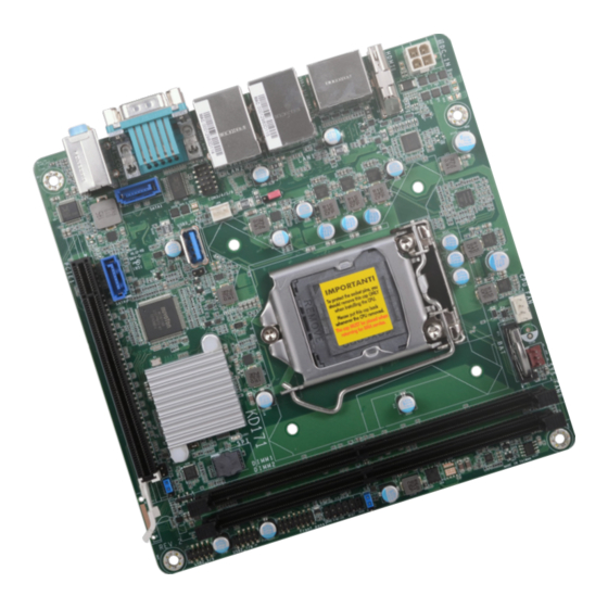
Chapter 2 - Hardware Installation KD171 www.dfi.com Chapter 2 - Hardware Installation ► Board Layout Important: Electrostatic discharge (ESD) can damage your board, pro- cessor, disk drives, add-in boards, and other components. CPU FAN Perform installation procedures at an ESD workstation only. -
Page 9: System Memory
Chapter 2 - Hardware Installation KD171 www.dfi.com ► System Memory ► System Memory Installing the DIMM Module Before installing the memory module, please make sure that the following safety cautions are well-attended. 1. Make sure the PC and all other peripheral devices connected to it has been powered down. -
Page 10: Removing The Dimm Module
Chapter 2 - Hardware Installation KD171 www.dfi.com ► System Memory ► Installing the DIMM Module ► System Memory Removing the DIMM Module Please follow the steps below to install the memory card into the socket. Step 1: Press the eject tabs at both ends of the socket outward and downward to release them from the Please follow the steps below to remove the memory card from the socket. -
Page 11: Cpu
Chapter 2 - Hardware Installation KD171 www.dfi.com ► CPU Installing the CPU 1. Make sure the PC and all other peripheral devices connected to it have been powered The system board is equipped with a surface mount LGA 1151 socket. This socket is exclu- down. - Page 12 Chapter 2 - Hardware Installation KD171 www.dfi.com ► CPU ► Installing the CPU ► CPU ► Installing the CPU Load lever 5. Lift the load lever and the load 7-2. Two keys on the sock- Alignment key plate all the way up as shown in et and notches on the photo.
-
Page 13: Installing The Fan And Heat Sink
Chapter 2 - Hardware Installation KD171 www.dfi.com ► CPU Installing the Fan and Heat Sink The CPU must be kept cool by using a CPU fan with heat sink. Without sufficient air circula- 4. Screw tight two of the spring screws at opposite corners into the mounting holes. And tion across the CPU and heat sink, the CPU will overheat damaging both the CPU and system then proceed with the other two spring screws. -
Page 14: Jumper Settings
Chapter 2 - Hardware Installation KD171 www.dfi.com ► Jumper Settings ME Disable Clear CMOS If any anomaly of the followings is encountered — a) CMOS data is corrupted; The 2-pin jack J1 is used to enable or disable Management Engine (ME). Put on a jumper cap to disable ME (default), or remove the jumper to enable ME. -
Page 15: Sata1 Power Select
Chapter 2 - Hardware Installation KD171 www.dfi.com SATA1 Power Select SATA1 SATA1 supports power supply via power cable or Disk on Module (DOM) to which power is supplied via Pin 7. To switch between the power supply mode, please configure the jumper settings as illustrated below. - Page 16 Chapter 2 - Hardware Installation KD171 www.dfi.com ► Rear I/O Ports 12V DC In ▼ HDMI ▼ LAN 1 ▼ LAN 2 ▼ COM 1 ▲ DC In coaxial ▲ DC In ▲ DP++ ▲ USB 3.0 ▲ USB 2.0 ▲...
-
Page 17: Rear I/O Ports
Chapter 2 - Hardware Installation KD171 www.dfi.com ► Rear I/O Ports ► Rear I/O Ports Graphics Display RJ45 LAN Ports ▼ LAN 1 ▼ LAN 2 ▲ HDMI ▲ DP++ DP++ The LAN ports allow the system board to connect to a local area network by means of a net- The DisplayPort is a digital display interface used to connect a display device such as a com- work hub. -
Page 18: Usb Ports
Chapter 2 - Hardware Installation KD171 www.dfi.com ► Rear I/O Ports ► Rear I/O Ports USB Ports COM (Serial) Ports ▼ COM 1/2 Pin Assignment RS232 DCD- DTR- DSR- RTS- ▲ USB 3.0 ▲ USB 2.0 CTS- ◄ COM 1 USB allows data exchange between your computer and a wide range of simultaneously acces- ◄... -
Page 19: Audio
Chapter 2 - Hardware Installation KD171 www.dfi.com ► Rear I/O Ports Audio Line-in Line-out Mic-in The system board is equipped a rear stacked audio jacks. • Line-in Jack (Light Blue) This jack is used to connect any audio devices such as Hi-fi set, CD player, tape player, AM/FM radio tuner, synthesizer, etc. -
Page 20: Internal I/O Connectors
Chapter 2 - Hardware Installation KD171 www.dfi.com ► Internal I/O Connectors ► Internal I/O Connectors Front Panel USB Ports ▼ USB 2.0 Pin Assignment ATX-SW RESET -Data -Data HD-LED +Data +Data PWR-LED N.C. ▼ USB 7/8 (upper) 5/6 ▲ Front Panel Connector (lower), USB 2.0... -
Page 21: Power
Chapter 2 - Hardware Installation KD171 www.dfi.com ► Internal I/O Connectors ► Internal I/O Connectors Power SATA (Serial ATA) Connectors ▼ SATA Power +12V Power ► ▼ 4-pin Power Pin Assignment ◄ SATA0 Assignment ▼ SATA1 +12V +12V The Serial ATA (SATA) connectors are used to connect the Serial ATA device. SATA 3.0 is sup- ported by the five SATA ports and provides data rate up to 6Gb/s. -
Page 22: Cooling Fan Connectors
Chapter 2 - Hardware Installation KD171 www.dfi.com ► Internal I/O Connectors ► Internal I/O Connectors Cooling Fan Connectors ▲ CPU Fan ▲ System Fan ▼ LPC Connector ▼ LPC Pin Assignment Pin Assignment Pin Assignment ▼ 3-pin Fan Pin Assignment ▼... -
Page 23: Expansion Slots
Chapter 2 - Hardware Installation KD171 www.dfi.com ► Internal I/O Connectors ► Internal I/O Connectors Expansion Slots Battery Battery PCIE1 (PCIe x16) PCI Express x16 Slot The lithium ion battery addendum supplies power to the real-time clock and CMOS memory as Install a PCI Express x16 graphics card that complies to the PCI Express specifications into the an auxiliary source of power when the main power is shut off. -
Page 24: Chapter 3 - Bios Setup
Chapter 3 - BIOS Settings KD171 www.dfi.com Chapter 3 - BIOS Setup ► Overview Legends The BIOS is a program that takes care of the basic level of communication between the CPU and peripherals. It contains codes for various advanced features found in this system board. -
Page 25: Main
Chapter 3 - BIOS Settings KD171 www.dfi.com ► Main ► Advanced The Main menu is the first screen that you will see when you enter the BIOS Setup Utility. The Advanced menu allows you to configure your system for basic operation. Some entries are defaults required by the system board, while others, if enabled, will improve the performance of your system or let you set some features according to your preference. -
Page 26: Acpi Configuration
Chapter 3 - BIOS Settings KD171 www.dfi.com ► Advanced ACPI Configuration InsydeH2O Setup Utility Rev. 5.0 InsydeH2O Setup Utility Rev. 5.0 Advanced Advanced ACPI Configuration Determines the action tak- ACPI Configuration Support display logo with ACPI BGRT table. en when the system power Wake On LAN <Disabled>... -
Page 27: Cpu Configuration
Chapter 3 - BIOS Settings KD171 www.dfi.com ► Advanced ► Advanced CPU Configuration Video Configuration Configure CPU processing related settings in this page. InsydeH2O Setup Utility Rev. 5.0 InsydeH2O Setup Utility Rev. 5.0 Advanced Advanced Initial priority : Video Configuration... -
Page 28: Audio Configuration
Chapter 3 - BIOS Settings KD171 www.dfi.com ► Advanced ► Advanced Audio Configuration SATA Configuration InsydeH2O Setup Utility Rev. 5.0 InsydeH2O Setup Utility Rev. 5.0 Advanced Advanced C o n t r o l D e t e c t i o n o f t h e H D -... -
Page 29: Usb Configuration
Chapter 3 - BIOS Settings KD171 www.dfi.com ► Advanced ► Advanced USB Configuration PCI Express Configuration InsydeH2O Setup Utility Rev. 5.0 InsydeH2O Setup Utility Rev. 5.0 Advanced Advanced U S B k e y b o a r d / m o u s e /... -
Page 30: Me Configuration
Chapter 3 - BIOS Settings KD171 www.dfi.com ► Advanced ► Advanced ME Configuration Debug Configuration Configure Management Engine related settings in this page. This section configures Debug setting. InsydeH2O Setup Utility Rev. 5.0 InsydeH2O Setup Utility Rev. 5.0 Advanced Advanced... -
Page 31: Uefi Device Manager
Chapter 3 - BIOS Settings KD171 www.dfi.com ► Advanced ► Advanced UEFI Device Manager SIO NUVOTON6116D Configure UEFI device with option ROM, such as LAN card, etc. Configure Super I/O settings in this submenu. Scroll by moving the cursor up or down to re- veal more options. - Page 32 Chapter 3 - BIOS Settings KD171 www.dfi.com ► Advanced ► SIO NUVOTON6116D ► Advanced ► SIO NUVOTON6116D Smart Fan PC Health Status Smart Fan is a fan speed moderation strategy that depends on the current system This section displays the PC health status.
-
Page 33: Console Redirection
Chapter 3 - BIOS Settings KD171 www.dfi.com ► Advanced Console Redirection COM1/COM2/COM3/COM4/COM5/COM6 Configure individual COM port serial settings in the submenu. Configure COM port serial settings in the submenu. InsydeH2O Setup Utility Rev. 5.0 InsydeH2O Setup Utility Rev. 5.0... -
Page 34: Security
Chapter 3 - BIOS Settings KD171 www.dfi.com ► Security ► Boot InsydeH2O Setup Utility Rev. 5.0 InsydeH2O Setup Utility Rev. 5.0 Main Advanced Security Boot Exit Main Advanced Security Boot Exit Current TPM Device <TPM 2.0 (FTPM)> W h e n H i d d e n , d o n ’ t e x - Numlock <On>... - Page 35 Chapter 3 - BIOS Settings KD171 www.dfi.com ► Boot ► Boot PXE Boot capability Legacy This field is only available when "Boot Type" is set to “UEFI Boot Type” or “Dual Boot Type”, Configure boot priorities in this submenu. Re-arrange the order by pressing -/+ or F5/F6 to and when "Network Stack"...
-
Page 36: Chapter 4 - Supported Software
Chapter 4 - Supported Software KD171 www.dfi.com Chapter 4 - Supported Software ► Intel Chipset Software Installation Utility Install drivers, utilities and software applications that are required to facilitate and enhance the The Intel Chipset Software Installation Utility is used for updating Windows INF files so that ®... -
Page 37: Intel Hd Graphics Drivers
Chapter 4 - Supported Software KD171 www.dfi.com ► Intel HD Graphics Drivers 3. Go through the readme docu- ment for more installation tips then click “Install”. 1. Setup is now ready to in- stall the graphics driver. Click “Next”. 4. The step displays the installing status in the progress. -
Page 38: Realtek Audio Drivers
Chapter 4 - Supported Software KD171 www.dfi.com ► Realtek Audio Drivers 3. Go through the readme docu- ment for system requirements and installation tips then click “Next”. 1. Setup is ready to install the driver. Click “Next”. 4. Setup is now installing the driver. -
Page 39: Realtek Lan Driver
Chapter 4 - Supported Software KD171 www.dfi.com ► Realtek LAN Driver 1. Setup is ready to install the driver. Click “Next”. 2. Click “Install” to begin the installation. 3. The step displays the installing status in the progress. -
Page 40: Intel Me Drivers
Chapter 4 - Supported Software KD171 www.dfi.com ► Intel ME Drivers 3. Click “Next” to install to the default folder, or click “Change” to choose another destination folder. 1. Setup is ready to install the driver. Click “Next”. 4. Please wait while the product is being installed. -
Page 41: Intel Serial Io Drivers
Chapter 4 - Supported Software KD171 www.dfi.com ► Intel Serial IO Drivers 3. Go through the readme docu- ment for system requirements and installation tips then click “Next”. 1. Setup is ready to install the driver. Click “Next”. 4. Setup is ready to install the driver. -
Page 42: Adobe Acrobat Reader 9.3
Chapter 4 - Supported Software KD171 www.dfi.com ► Adobe Acrobat Reader 9.3 5. Setup is now installing the driver. 1. Click “Next” to install or click “Change Destination Folder” to select another folder. 6. Click “Yes, I want to restart this computer now”... -
Page 43: Intel Rapid Storage Technology
Chapter 4 - Supported Software KD171 www.dfi.com ► Intel Rapid Storage Technology The Intel Rapid Storage Technology is a utility that allows you to monitor the current status of the SATA drives. It enables enhanced performance and power management for the storage subsystem. - Page 44 Chapter 4 - Supported Software KD171 www.dfi.com 3. Go through the readme docu- 6. Click “Yes, I want to restart ment to view system require- this computer now” to com- ments and installation informa- plete the installation and then tion then click “Next”.
-
Page 45: Chapter 5 - Raid
Chapter 5 - RAID KD171 www.dfi.com Chapter 5 - RAID ► Setup Procedure The system board allows configuring RAID on Serial ATA drives. It supports RAID 0, RAID 1, To enable the RAID function, the following settings are required. RAID 5 and RAID 10. - Page 46 Chapter 5 - RAID KD171 www.dfi.com ► Setup Procedure ► Setup Procedure Step 3: Create a RAID Volume Step 3-1: Create a RAID Volume in UEFI Mode 1. When the Intel RST option ROM status screen displays during POST, press <Ctrl> and If the boot type is set to UEFI, RAID volume creation will be different.
- Page 47 Chapter 5 - RAID KD171 www.dfi.com ► Setup Procedure Step 4: Install Intel Rapid Storage Technology The Intel Rapid Storage Technology can be installed from within Windows. It allows you to display, manage (create, delete, migrate), and monitor SATA and RAID volume via user-friendly and icon-driven UI, and enables enhanced performance and power management for your stor- age subsystems.
Need help?
Do you have a question about the KD171 and is the answer not in the manual?
Questions and answers