
Related Manuals for DFI KD630-H110


Summary of Contents for DFI KD630-H110
- Page 1 KD630-H110 ATX Industrial Motherboard User’s Manual A-613-M-2102 ver.021_EVT_11-3020_14-53...
- Page 2 Copyright FCC and DOC Statement on Class B This publication contains information that is protected by copyright. No part of it may be repro- This equipment has been tested and found to comply with the limits for a Class B digital duced in any form or by any means or used to make any transformation/adaptation without the device, pursuant to Part 15 of the FCC rules.
-
Page 3: Table Of Contents
Table of Contents Chapter 4 - RAID ................................34 RAID Levels ................................34 Setup Procedure ..............................34 Chapter 1 - Introduction ..............................6 Specifications ................................6 Features ..................................7 Block Diagram ................................8 Chapter 2 - Hardware Installation ..........................8 Board Layout ................................8 LED and Switch ................................8 System Memory .................................9 Installing the DIMM Module ........................9 Removing the DIMM Module ........................10 CPU ....................................11... - Page 4 About this Manual Static Electricity Precautions This manual can be downloaded from the website. It is quite easy to inadvertently damage your PC, system board, components or devices even before installing them in your system unit. Static electrical discharge can damage computer The manual is subject to change and update without notice, and may be based on editions that components without causing any signs of physical damage.
- Page 5 The package contains the following items. If any of these items are missing or damaged, components. please contact your dealer or sales representative for assistance. • Memory module • 1 KD630-H110 motherboard • Storage device such as a hard disk drive. • 1 COM port cable (Length: 300mm, 2 x COM ports) •...
-
Page 6: Chapter 1 - Introduction
Chapter 1 INTRODUCTION Chapter 1 - Introduction GRAPHICS Controller Intel® HD Gen 9 Graphics Feature OpenGL 5.0, DirectX 12, OpenCL 2.1 X Specifications HW Decode: AVC/H.264, MPEG2, VC1/WMV9, JPEG/MJPEG, HEVC/H265, VP8, VP9 HW Encode: MPEG2, AVC/H264, JPEG, HEVC/H265, VP8, VP9 SYSTEM Processor 7th Gen Intel®... - Page 7 Chapter 1 INTRODUCTION SATA 4 x SATA 3.0 (up to 6Gb/s) 1 x 8-bit DIO 1 x LPC (supports LPC EXT-RS232/RS485 module) SMBus 1 x SMBus WATCHDOG Output & System Reset, Programmable via Software from 1 to 255 TIMER Interval Seconds SECURITY Infineon TPM2.0/1.2 (opt., MOQ required)
-
Page 8: Features
Chapter 1 INTRODUCTION X Features Watchdog Timer PCI Express The Watchdog Timer function allows your application to regularly “clear” the system at the set PCI Express is a high bandwidth I/O infrastructure that possesses the ability to scale speeds time interval. If the system hangs or fails to function, it will reset at the set time interval so that by forming multiple lanes. -
Page 9: Block Diagram
Chapter 1 INTRODUCTION X Block Diagram Channel A DDR4 up to 2666MHz DVI-I UDIMM Core R.G.B PIN3355 i7/i5/i3 Channel B DDR4 up to 2666MHz UDIMM TMDS HDMI ASM1442 PCIe x16 Gen3 PCIe x16 PCIe x1 SATA 3.0 SATA 3x GLAN 1 I219V PCIe x1 GLAN 2... -
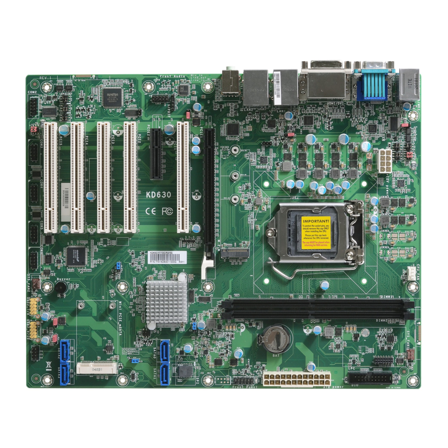
Page 10: Chapter 2 - Hardware Installation
Chapter 2 HARDWARE INSTALLATION Chapter 2 - Hardware Installation X Board Layout Note: Some components are optional and only available upon request. COM 1 RS232/422/485 Select (JP3) CPU Fan System PS/2 KB/MS JP15 COM 1 RS232/Power Select (JP4) Fan 1 USB 5-6 USB 2.0 COM 1 RS232/422/485... -
Page 11: System Memory
Chapter 2 HARDWARE INSTALLATION System Memory X System Memory Installing the DIMM Module Before installing the memory module, please make sure that the following safety cautions are well-attended. Make sure the PC and all other peripheral devices connected to it has been powered down. -
Page 12: Removing The Dimm Module
Chapter 2 HARDWARE INSTALLATION System Memory Installing the DIMM Module System Memory Removing the DIMM Module Please follow the steps below to install the memory card into the socket. Please follow the steps below to remove the memory card from the socket. Step 1: Press the eject tabs at both ends of the socket outward and downward to release them from Step 1:... -
Page 13: Cpu
Chapter 2 HARDWARE INSTALLATION X CPU The system board is embedded with a AMD® EPYC™ Embedded CPU. Installing the CPU Fan and Heat Sink The CPU must be kept cool by using a CPU fan with heat sink. Without sufficient air circula- tion across the CPU and heat sink, the CPU will overheat damaging both the CPU and system board. -
Page 14: Jumper Settings
Chapter 2 HARDWARE INSTALLATION Jumper Settings X Jumper Settings CLEAR CMOS Data USB Power Select 1-2 On: +5VDU (default) JP15 M.2 M Key 2-3 On: +5V JP11 M.2 M Key 1-2 On: +5VDU (default) JP12 If any anomaly of the followings is encountered — a) CMOS data is corrupted;... - Page 15 Chapter 2 HARDWARE INSTALLATION Jumper Settings „ JP3 (COM1)/JP10 (COM2) 2 4 6 2 4 6 2 4 6 COM1/COM2 RS232/422/485 Select 1 3 5 1 3 5 1 3 5 (COM 1) 1-3, 4-6 On: 3-5, 4-6 On: 3-5, 2-4 On: RS232 (default) (COM 1) (COM 1)
- Page 16 Chapter 2 HARDWARE INSTALLATION Jumper Settings „ JP4 (COM 1) 2 4 6 2 4 6 COM1/COM2 RS232 Power Select 1 3 5 1 3 5 (COM 1) 1-3, 2-4 On: 3-5, 4-6 On: RS232 (default) RS232 with power „ JP7 (COM 2) 2 4 6 2 4 6 M.2 M Key...
- Page 17 Chapter 2 HARDWARE INSTALLATION Jumper Settings Jumper Settings SATA/mSATA Signal Select PCIe/M.2 Signal Select 1-2 On: PCIe (default) M.2 M Key M.2 M Key 1-2 On: JP16 SATA (default) JP16 2-3 On: M.2 (default) 2-3 On: mSATA JP16 is used to select the SATA/mSATA signal: SATA (default) or mSATA. JP18 is used to select the PCIe/M.2 signal: PCIe (default) or M.2.
-
Page 18: Rear I/O Ports
Chapter 2 HARDWARE INSTALLATION Rear I/O Ports X Rear I/O Ports PS/2 Keyboard/Mouse Port DVI-I (DVI-D signal) LAN 1 LAN 2 COM 1 PS/2 KB/MS PS/2 KB/MS Line-out USB 2.0 Mic-in HDMI USB 3.1 USB 3.1 Gen 1 Gen 1 The rear panel I/O ports consist of the following: M.2 M Key •... -
Page 19: Com (Serial) Ports
Chapter 2 HARDWARE INSTALLATION Rear I/O Ports COM (Serial) ports The pin functions of COM 1 port will vary according to setting of JP1, JP2, JP3 and JP4. Refer to “COM1/COM2 RS232/422/485 Select” and “COM1/COM2 RS232/Power Select” in this chap- ter for more information. - Page 20 Chapter 2 HARDWARE INSTALLATION Rear I/O Ports USB Ports „ USB 2.0 Headers (USB 7/8) Assignment Assignment SBV3 SBV3 USB 5 (USB 2.0) USBP_C_7- USBP_C_8- USB 6 (USB 2.0) USBP_C_7+ USBP_C_8+ N.C. M.2 M Key „ USB 2.0 Headers (USB 9/10) Assignment Assignment SBV5...
- Page 21 Chapter 2 HARDWARE INSTALLATION Rear I/O Ports Graphics Interfaces VGA Port The VGA port is used for connecting a VGA monitor. Connect the monitor’s 15-pin D-shell cable The display ports consist of the following: connector to the VGA port. After you plug the monitor’s cable connector into the VGA port, gen- tly tighten the cable screws to hold the connector in place.
-
Page 22: Rj45 Lan Ports
Chapter 2 HARDWARE INSTALLATION Rear I/O Ports Rear I/O Ports RJ45 LAN Ports Audio LAN 1 LAN 2 Line-out Rear Audio M.2 M Key Mic-in Front M.2 M Key Audio Mic2-L Mic2-R Mic2-JD Line2-R Front I/O Sense Line2-L Line2-JD Rear Audio The system board is equipped with 2 audio jacks (Line-out and Mic-in). -
Page 23: Internal I/O Connectors
Chapter 2 HARDWARE INSTALLATION Internal I/O Connectors X Internal I/O Connectors SATA (Serial ATA) Digital I/O Connector SATA Pin Assignment „ M.2 M Key M.2 M Key SATA 0/1 from left to right SATA 2/3 from left to right The 8-bit Digital I/O connector provides powering-on function to external devices that are con- nected to these connectors. -
Page 24: Cooling Fan Connectors
Chapter 2 HARDWARE INSTALLATION Internal I/O Connectors Internal I/O Connectors Cooling Fan Connectors Power Connector CPU Fan (PWM) System Fan 1 (PWM) „ ATX 8-pin Power Connectors +12V 12 24 +3.3V +12V „ CPU Fan +12V +5VSB PWR_OK M.2 M Key PS_ON# M.2 M Key +3.3V... -
Page 25: Chassis Intrusion
Chapter 2 HARDWARE INSTALLATION Internal I/O Connectors Internal I/O Connectors Chassis Intrusion Front Panel „ Front Panel Connector PWR-LED ATX-SW M.2 M Key M.2 M Key HD-LED RESET „ J4 Chassis Intrusion „ Front Panel Pin Assignment Assignment Assignment N.C. 3V3SB PWR-LED 3V3SB... - Page 26 Chapter 2 HARDWARE INSTALLATION Internal I/O Connectors Internal I/O Connectors LAN LED Connector S/PDIF Connector „ J1 S/PDIF M.2 M Key M.2 M Key SPDIF out SPDIF in „ J15 LAN LED The LAN LED connector is used to detect the connection state of RJ45 LAN ports when the The S/PDIF connector is used to connect an external S/PDIF port.
- Page 27 Chapter 2 HARDWARE INSTALLATION Internal I/O Connectors Internal I/O Connectors SMBus Connector LPC Connector „ LPC Connector „ J13 SMBus M.2 M Key M.2 M Key SMB_ALERT SMB_DATA SMB_CLK 3V3DU The SMBus (System Management Bus) connector is used to connect SMBus devices. It is a The Low Pin Count Interface was defined by Intel ®...
- Page 28 Chapter 2 HARDWARE INSTALLATION Internal I/O Connectors Internal I/O Connectors SPI PROGRAM HEADER (OPTIONAL) - J23 M.2 M Key M.2 M Key „ SPI PROGRAM HEADER - J23 „ J5 Pin Assignment Pin Assignment Assignment Assignment Assignment Assignment Signal V_3P3_SPI ICHSPI_CS0- SPI_CLK-R SPI_SO-R...
-
Page 29: Expansion Slots
Chapter 2 HARDWARE INSTALLATION Internal I/O Connectors Internal I/O Connectors Expansion Slots Expansion Slots Installing the M.2 Module Before installing the M.2 module into the M.2 socket, please make sure that the following safety cautions are well-attended. Make sure the PC and all other peripheral devices connected to it has been powered PCIe 1 (PCIe x16) down. -
Page 30: Battery
Chapter 2 HARDWARE INSTALLATION Internal I/O Connectors Expansion Slots Internal I/O Connectors Battery Please follow the steps below to install the card into the socket. Step 1: Insert the card into the socket „ Battery at an angle while making sure the notch and key are perfectly aligned. -
Page 31: Chapter 3 - Bios Setup
Chapter 3 BIOS SETTINGS Chapter 3 - BIOS Setup Legends X Overview The BIOS is a program that takes care of the basic level of communication between the CPU Keys Function and peripherals. It contains codes for various advanced features found in this system board. The BIOS allows you to configure the system and save the configuration in a battery-backed Right / Left arrow Move the highlight left or right to select a menu... -
Page 32: Main
Chapter 3 BIOS SETTINGS X Main X Advanced The Main menu is the first screen that you will see when you enter the BIOS Setup Utility. The Advanced menu allows you to configure your system for basic operation. Some entries are defaults required by the system board, while others, if enabled, will improve the performance of your system or let you set some features according to your preference. -
Page 33: Acpi Configuration
Chapter 3 BIOS SETTINGS Advanced ACPI Configuration InsydeH2O Setup Utility Rev. 5.0 InsydeH2O Setup Utility Rev. 5.0 Advanced Advanced Wake on PS/2 device ACPI Configuration ACPI Configuration Determines the action tak- en when the system power Wake On LAN <Enabled> Wake On LAN <Enabled>... -
Page 34: Cpu Configuration
Chapter 3 BIOS SETTINGS Advanced Advanced CPU Configuration Video Configuration Configure CPU processing related settings in this page. InsydeH2O Setup Utility Rev. 5.0 InsydeH2O Setup Utility Rev. 5.0 Advanced Advanced Initial priority : Video Configuration CPU Configuration Allows more than two AUTO: PEG->PCIe->PCI->IGFX f r e q u e n c y r a n g e s t o b e IGFX: IGFX->PEG->PCIe->PCI... -
Page 35: Sata Configuration
Chapter 3 BIOS SETTINGS Advanced Advanced Audio Configuration SATA Configuration InsydeH2O Setup Utility Rev. 5.0 InsydeH2O Setup Utility Rev. 5.0 Advanced Advanced Audio Configuration Control Detection of the SATA Controller <Enabled> Enable or Disable SATA HD-Audio device. SATA Speed Device. <Auto>... -
Page 36: Usb Configuration
Chapter 3 BIOS SETTINGS Advanced Advanced PCI Express Configuration USB Configuration InsydeH2O Setup Utility Rev. 5.0 InsydeH2O Setup Utility Rev. 5.0 Advanced Advanced U S B k e y b o a r d / m o u s e / s t o r a g e USB Configuration PCI Express Configuration PCI Express Port Settings... - Page 37 Chapter 3 BIOS SETTINGS Advanced ME Configuration InsydeH2O Setup Utility Rev. 5.0 Advanced Enable/disable to flash ME ME Fw Image Re-Flash <Disabled> region Help ↑ /↓ Select Item F5/F6 Change Values Setup Defaults Exit ←/→ Select Item Enter Select SubMenu Save and Exit Me Fw Image Re-Flash This field is used to enable or disable the flash ME region.
-
Page 38: Debug Configuration
Chapter 3 BIOS SETTINGS Advanced Advanced Debug Configuration UEFI Device Manager This section configures Debug setting. Configure UEFI device with option ROM, such as LAN card, etc. InsydeH2O Setup Utility Rev. 5.0 InsydeH2O Setup Utility Rev. 5.0 Advanced Advanced Enable it to output debug mes- UEFI Device Manager Setting Debug Configuration UEFI Device Manager... - Page 39 Chapter 3 BIOS SETTINGS Advanced SIO NUVOTON6106D InsydeH2O Setup Utility Rev. 5.0 Advanced This section configures the system super I/O chip parameters. Configure Serial port using op- Fan Speed Count 3 [50] tions: [Disable] No Configura- Fan Speed Count 4 [75] tion [Enable] User Configuration COM Port 1...
- Page 40 Chapter 3 BIOS SETTINGS Advanced SIO NUVOTON6106D X PC Health Status This section displays the PC health status. InsydeH2O Setup Utility Rev. 5.0 Advanced PC Health Status Voltage VBAT 3.040 V VCORE 1.008 V VDDQ 1.200 V 5.056 V +12V 12.144 V Temperature System (°C/°F)
-
Page 41: Console Redirection
Chapter 3 BIOS SETTINGS Advanced X COM1/COM2/J1 Console Redirection Configure individual COM port serial settings in the submenu. Configure COM port serial settings in the submenu. InsydeH2O Setup Utility Rev. 5.0 InsydeH2O Setup Utility Rev. 5.0 Advanced Advanced E n a b l e C o n s o l e R e d i r e c t i o n Console Redirection Setup COM1 Function... -
Page 42: Security
Chapter 3 BIOS SETTINGS X Security X Boot InsydeH2O Setup Utility Rev. 5.0 InsydeH2O Setup Utility Rev. 5.0 Main Advanced Security Boot Exit Security Current TPM Device <TPM 2.0 (FTPM)> W h e n H i d d e n , d o n ’ t e x - Numlock <On>... - Page 43 Chapter 3 BIOS SETTINGS Boot PXE Boot capability This field is only available when "Boot Type" is set to “UEFI Boot Type” or “Dual Boot Type”, and when "Network Stack" is enabled. Disabled Suppoort Network Stack UEFI IPv4 UEFI IPv6 UEFI IPv4/IPv6 USB Boot...
-
Page 44: Exit
BIOS with the flash utility. For updating Insyde BIOS in UEFI mode, you may refer to the how-to video at https://www.dfi.com/tw/knowledge/video/31. InsydeH2O Setup Utility Rev. 5.0... - Page 45 Chapter 4 RAID SETTINGS Chapter 4 - RAID X Setup Procedure The system board allows configuring RAID on Serial ATA drives. It supports RAID 0, RAID 1, and SPAN. To enable the RAID function, the following settings are required. Install SATA drives. Enter the RAID menu X RAID Levels Create RAID 0/RAID 1/SPAN...
- Page 46 Chapter 4 RAID SETTINGS Setup Procedure Setup Procedure Wait the process to start, the whole process takes about several seconds depends on Step 3: Create RAID 0/RAID 1/ SPAN the volume amounts. Select the desired mode and press <Enter>. 4. "*" shown on bottom indicates the progress. Press <Y>...
- Page 47 Chapter 4 RAID SETTINGS 5. Relevant information will appear with the message "Mode change is completed." on bot- tom. Other RAID modes follow the same procedure as well. User's Manual | KD630...
Need help?
Do you have a question about the KD630-H110 and is the answer not in the manual?
Questions and answers