RUPTELA HCV5 Quick Start Manual
Tachograph solution
For more information, please visit ruptela.com
Hide thumbs
Also See for HCV5:
- User manual (50 pages) ,
- Quick start manual (6 pages) ,
- Connection instructions (4 pages)
Advertisement
This quick start guide is only for the direct connection. For connection via the front interface, please refer
to the
user
manual.
Make sure that you have:
•
A vehicle with one of the following tachographs:
Siemens VDO 1381 (versions higher than 1.3A)
o
Stoneridge SE5000 (versions higher than 7.0)
o
EFAS-4 or newer
o
•
A computer with Windows 7/8/10
•
An internet connection (or a predownloaded
•
A USB A to USB micro (Type B) cable
•
A
tachograph harness
Device overview
Indication LEDs
GNSS antenna port
Audio port
Indication LED patterns
LED
Pattern
GNSS
Once every second
Once every 0.4 seconds
Cellular
Once every 4 seconds
Once every second
Once every 0.2 seconds
Always on
Peripherals
Always off
Once every 5 seconds
Twice every 5 seconds
Three times every 5 seconds
All
Once every 5 seconds
www.ruptela.com
Tachograph Solution
Quick Start Guide
Q
Device
(recommended)
Opening handles
16 Pin port
14 Pin port
Description
Accurate signal
No signal
Connected to network and internet
Connected to network, no internet
No signal
Link with the server is open
No devices connected
One device connected
Two devices connected
Three devices connected
Sleep mode
support@ruptela.com | +370 5 2045030
Center)
Grooves for zip-ties
Micro USB port
HCV5
1
Advertisement
Table of Contents

Related Manuals for RUPTELA HCV5


Summary of Contents for RUPTELA HCV5
- Page 1 Peripherals Always off No devices connected Once every 5 seconds One device connected Twice every 5 seconds Two devices connected Three times every 5 seconds Three devices connected Once every 5 seconds Sleep mode www.ruptela.com support@ruptela.com | +370 5 2045030...
-
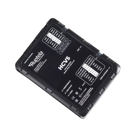
Page 2: Device Pinout
Analogue input 1 DOUT3 White/Purple Digital output 3 CAN2-H White CAN High DOUT4 White/Orange Digital output 4 SW CAN Green/White Single-Wire CAN AIN3 White/Grey Analogue input 3 CAN1-H White/Red CAN High 1W+5V Red/ Yellow 1-Wire power www.ruptela.com support@ruptela.com | +370 5 2045030... - Page 3 Connect the device to your computer using a USB Select your device. cable. Click Connect device. Open the Connection settings. Configure Fleet Management System Main Server settings (TrustTrack server settings are entered by default). Configure GSM provider APN settings. www.ruptela.com support@ruptela.com | +370 5 2045030...
- Page 4 Turn on the CAN1, CAN2 and K-Line interfaces in Vehicle interface settings. Tacho read If you are using the tachograph harness, for CAN1 set the mode. Select the required Baudrate. Click Save to device to upload the config to the device. www.ruptela.com support@ruptela.com | +370 5 2045030...
-
Page 5: Installation
If • Avoid installing near metal surfaces the status is red, click the Troubleshoot button for troubleshooting. Incorrect Correct Check what parameters are received by clicking Details in the CAN/K-Line Interfaces section. www.ruptela.com support@ruptela.com | +370 5 2045030... -
Page 6: Wiring Diagram
CAN tacho driver2 card • TCO second driver state Further reading • Documentation website: https://doc.ruptela.lt/ • User manual: https://doc.ruptela.lt/pages/viewpage.action?pageId=37683334 • Device Center: https://doc.ruptela.lt/display/AB/Device+Center We highly recommend you read the user manual before using the device. www.ruptela.com support@ruptela.com | +370 5 2045030... -
Page 7: Frequently Asked Questions
(socket C, pins 5, 7, 8). Legal information Copyright © 2021 Ruptela. All rights reserved. Reproduction, transfer, distribution or storage of parts or all of the contents in this document in any form without the prior written permission of Ruptela is prohibited. Other products and company names mentioned in this document are trademarks or trade names of their respective owners.
Need help?
Do you have a question about the HCV5 and is the answer not in the manual?
Questions and answers