RUPTELA FM-Pro4 User Manual
For more information, please visit ruptela.com
Hide thumbs
Also See for FM-Pro4:
- User manual (42 pages) ,
- User manual (30 pages) ,
- Quick start manual (4 pages)
Table of Contents
Advertisement
Advertisement
Table of Contents

Related Manuals for RUPTELA FM-Pro4


Summary of Contents for RUPTELA FM-Pro4
-
Page 2: Table Of Contents
Advanced configuration ......................18 4.3.1 Global settings ....................... 19 4.3.2 Profile settings ....................... 24 4.3.3 IO settings ........................29 Integration protocol ......................35 Installation recommendations ....................... 36 Device installation ......................... 36 FM-Pro4 BT device ........................ 36 Antenna installation ......................36... -
Page 3: Preface
“Global settings” chapter. Added “CAN HCV” and “DXP CAN” modes descriptions in the “IO settings” 2016-10-14 chapter. Information about FM-Pro4 BT device in “Technical characteristics”, “Global 2016-11-29 settings” and “Installation recommendations” chapters. 2016-12-13 “Constant TCP link” functionality description in “Profile settings” chapter. -
Page 4: Introduction
Copyright © 2016 Ruptela. All rights reserved. Reproduction, transfer, distribution or storage of parts or all of the contents in this document in any form without the prior written permission of Ruptela is prohibited. Other products and company names mentioned in this document are trademarks or trade names of their respective owners. -
Page 5: References
12/24 V DC. The allowed voltage range from the battery is from 10 volts to 32 volts DC. Max. current for FM-Pro4 is 250 mA @ 12 V DC. Max. current for FM-Pro4 3G / Pro4 BT is 350 mA @ 12 V To avoid mechanical damage, it is advised to transport the FM terminal in an impact-proof package. - Page 6 – This additional software is required in order to run our configurator. VCOM drivers – Drivers required for device connection to PC. All links are also provided in corresponding sections, where additional information might be needed. Note Ruptela documentation website address: doc.ruptela.lt...
-
Page 7: Device Description
It acquires it’s position by a GPS/GLONASS signal and transfers data to a server via cellular 3G or GSM/GPRS network. 3G network support was not previously available for FM4 devices. This new feature in FM-Pro4 3G is the main advantage over the FM-Pro4 devices. -
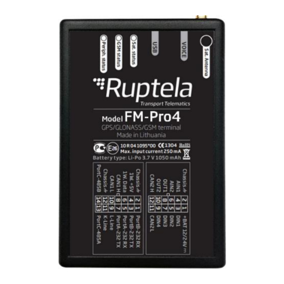
Page 8: Physical Characteristics
3 LEDs: Sat. status, GSM status, Periph. status Housing Plastic External elements GPS/GLONASS all-in-one antenna Configuration interface Connectors 12 & 14 PINs 3.4 Technical characteristics Power consumption @ 12V FM-Pro4 FM-Pro4 BT FM-Pro4 3G Idle mode, mA Sending records, mA Deep sleep mode, mA... - Page 9 If temp is >45C, charging is disabled, if >60C battery is disconnected from the system at all. Only for the FM-Pro4 3G device. Only for the FM-Pro4 BT device. Feature is currently under development. Not soldered in standard version. Can be ordered.
-
Page 10: Io Pin Out
3.5 IO pin out 12 PIN connector Pin nr Wire color Description 10-32 V Power supply 12/24 V (range: 10-32 V) Chassis Black Ground connection DIN1 Pink Digital input, threshold 4 V AIN1 Gray Analogue input (range: 0-30 V) DIN2 Blue Digital input, threshold 4 V AIN2... -
Page 11: Interfaces And Peripheral Accessories
Note Maximum 1-Wire interface power output is 200 mA @ 5 V. FM-Pro4 / Pro4 3G / Pro4 BT device support RS232, RS485, 1-wire and CAN interfaces. List of available peripherals devices that can be to them: Available on 1-Wire: 4 ×... -
Page 12: Certification
Only FM-Pro4 BT devices have built in Bluetooth module. You can find peripheral accessories installation instructions and documentation on our documentation website. 3.7 Certification FM-Pro4 / Pro4 3G / Pro4 BT devices have passed quality tests and comply with following certifications: Certification FM-Pro4 FM-Pro4 BT... -
Page 13: Peripheral Led
When device has a good GSM signal, but no GPRS, LED is blinking as follows: When device has good GSM signal and it is connected to GPRS, then LED is blinking as follows: When the device terminal has GSM signal and it is sending data via GPRS, LED is blinking: 3.8.3 Peripheral LED The device terminal can have up to 3 peripheral devices attached to it (e.g. -
Page 14: Led Status In Sleep And Deep Sleep Modes
3.8.4 LED status in sleep and deep sleep modes When device is in sleep / deep sleep mode all three LEDs blink at the same time in the following pattern:... -
Page 15: Device Configuration
4 Device configuration 4.1 Driver installation Virtual COM port driver installation is mandatory, only then your PC will recognize the FM-Pro4 / Pro4 3G / Pro4 BT device that was connected to the USB port. You can download newest drivers on our... - Page 16 Wait for the setup to complete the installation and click “Finish” [5.]. Driver is now installed and ready to use.
-
Page 17: Sample Configuration
Microsoft Framework. Operating system requirements: MS Windows XP/Vista/7/8 Example for FM-Pro4 / Pro4 3G: Start the VCP.exe from configurator folder. Select Pro4. Click File → Open CFG. In dialog window, browse the sample configuration file you downloaded from the documentation website. - Page 18 Procedure for Pro4 BT device is very similar. Download configurator and sample configuration file for the FM-Pro4 BT device. In configurator select Pro4 BT and open “Standard config PRO BT (for clients).ff4c” file. Sample parameters will be loaded. However you will need to enter other parameters on your own.
-
Page 19: Advanced Configuration
4.3 Advanced configuration The configuration tool is quite similar to the ones used for other 3 generation devices. Overview of the configuration is described in sections. The “File” menu gives you access to control New/Save/Open CFG configuration files. Choose perform the corresponding action. CFG means full configuration file. -
Page 20: Global Settings
4.3.1 Global settings The first part of the configuration tool is “Global” settings. Global include connection settings and other settings independent from the profile settings – global settings are the same for all profiles. Connection settings here you should enter server IP and port that the device should connect to. The IP can be entered in the numeric format: 255.255.255.255. - Page 21 Note Two server mode doubles the amount of data that is being sent. Before using this functionality consider the cost which arises from the higher data traffic. Protocol sections allows you to choose from two protocols. UDP protocol is less reliable than the TCP, but also uses less traffic.
- Page 22 Configuration password allows to lock the configuration – without the password no one can change the device configuration via cable. However, over-the-air update ignores the configuration password. Driver registration is used to authorize vehicle start, identify driver and account working hours. Full functionality description can be found at our documentation website, Driver registration.
- Page 23 If you check Enable list for voice calls entered numbers will be able to make a call through the device. Note FM-Pro4 3G has no audio interface, therefore audio transmission is not available. Enable configuration over SMS checkbox controls configuration over the SMS feature.
- Page 24 Wireless Note Wireless section is available only for FM-Pro4 BT device, which has built in Bluetooth module. Wireless section contains Bluetooth communication settings. Add a tick to the Enable check box to make your FM-Pro4 BT device discoverable by other Bluetooth devices. Click “Options” button to change basic wireless communication settings.
-
Page 25: Profile Settings
OnTrack Connect app user manual available here. Connection PIN – You need to know this code in order to pair your smartphone with FM-Pro4 BT device. In “OnTrack Connect” choose your unpaired FM device and enter this PIN code. - Page 26 Min. records – Minimum number of records required to establish a connection to the server. If the device detects less records than entered value, link to the server will not be opened. Period – sets how often the device will check for required number of records. Link timeout –...
- Page 27 Data collection must be enabled to collect the information. Time without engine means how often records should be made, when the engine is off. The Engine drop box allows you to choose how the device will pick up the ignition (consider that the engine is on).
- Page 28 – Device operates only in 2G mode. UMTS only – Device operates only in 3G mode. Note FM-Pro4 devices with hardware versions that do not have UG96 modem operate only in 2G mode. For these devices “Auto”, “GSM only” “UMTS only”...
- Page 29 GPRS Attempt – how many times device will try to attach to operator`s GPRS before trying another operator. GPRS data counter – how many kilobytes of data device should send before performing next operator search. Temporary blacklist – temporal ban period in seconds. Sometimes when the FM device connects to the operator with unavailable GPRS, the device is connected, but cannot transmit any data to the server.
-
Page 30: Io Settings
4.3.3 IO settings IO events “Options” buttons opens up a new “IO settings” window, here you can enable or disable IO parameters that will be sent to a server. You have 80 slots for parameters. Select a slot that you want to enable. In the IO properties section tick the Enable check box, otherwise the slot will remain empty. - Page 31 Protocol selection section has a checkbox, where you can choose to “Send I/O data with v1.1 protocol”. Note Enabling this checkbox will result in the loss of all unsent records. Interfaces section gives ability to enable or disable all of the device’s interfaces (described in 3.6 paragraph).
- Page 32 CAN – if you put a tick in the 1st CAN interface checkbox, then a dropdown list appears, where you can choose one of the following: FMS - for vehicle CANbus (FMS) information reading. HCV - for HCV CAN (heavy commercial vehicles) information reading. DXP CAN –...
- Page 33 HCV Group selection dropdown list. HCV Sub group selection dropdown list. ? – HCV selection by vehicle brand, model and year. Something to consider, when Smart CAN IO Selection turned on: With HCV mode set on the CAN interface, only specific CAN IO parameters that are supported for currently selected HCV Group and Subgroup will be visible.
- Page 34 Calc HRLFC - enables fuel consumption recalculation from fuel rate for FMS CANbus mode. Recalculation works only when high resolution fuel consumption data from CANbus is not available. Active – If this checkbox is enabled, device will do both, receive and send data to the vehicle’s onboard computer.
- Page 35 DXP CAN: This mode can be used to read CANbus information from electric DXP vehicles. Disable Smart CAN IO Selection The section itself and the “Disable” button will be visible only when one of the CAN interfaces is enabled DXP CAN J1708 and the mode is selected.
-
Page 36: Integration Protocol
4.4 Integration protocol All integration related questions and documentation can be acquired from Ruptela technical support: support@ruptela.com... -
Page 37: Installation Recommendations
To ensure the best possible connectivity between Bluetooth devices follow these steps: FM-Pro4 BT device with Bluetooth module should be installed facing up. Please avoid mounting it near metal surfaces or cables.
Need help?
Do you have a question about the FM-Pro4 and is the answer not in the manual?
Questions and answers