RUPTELA FM-Eco4 User Manual
For more information, please visit ruptela.com
Hide thumbs
Also See for FM-Eco4:
- User manual (50 pages) ,
- Quick start manual (4 pages) ,
- User manual (33 pages)
Table of Contents
Advertisement
Quick Links
Advertisement
Table of Contents

Related Manuals for RUPTELA FM-Eco4


Summary of Contents for RUPTELA FM-Eco4
-
Page 2: Table Of Contents
Preface ..............................2 Use of this document ........................2 Document change log ........................2 Introduction ............................3 Purpose ............................3 Acronyms ............................3 Legal Information .......................... 3 Safety ............................3 References ............................ 4 Device description ..........................5 About ............................. 5 Package contents .......................... -
Page 3: Preface
This document provide required information for proper device handling, preparation, configuration and installation to vehicle. This document has linear structure – from opening box to recommendations how to install device to vehicle. However it is not overfilled with unnecessary information. You will find basic description of functions and actions to start using device with reference to extensive content descriptions. -
Page 4: Introduction
Copyright © 2014 Ruptela. All rights reserved. Reproduction, transfer, distribution or storage of parts or all of the contents in this document in any form without the prior written permission of Ruptela is prohibited. Other products and company names mentioned in this document are trademarks or trade names of their respective owners. -
Page 5: References
Any installation and/or handling during a lightning storm is prohibited. For configuration use cables that were purchased from Ruptela. Ruptela is not responsible for any harm caused, while using wrong cables for the PC ↔ Terminal connection. Attention! Do not connect the wires marked red (power supply) and black (chassis) to the wrong battery poles. -
Page 6: Device Description
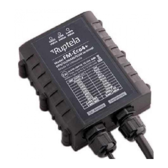
• USB cable (as optional accessory) Figure 2. Box contents: FM-Eco4/4+ device, GPS/GLONASS antenna, IO cable, USB cable (optional accessory) Providing SIM card is optional, according to your payment plan. SIM card is necessary for connection to the GSM network! SIM card can be obtained from your local GSM service provider! SIM card can... -
Page 7: Physical Characteristics
0 - +45 Battery discharging -20 - +60 × Power supply 10-32 V DC Absolute maximum ratings (on FM-Eco4+) 50 V @ 60 s 72 V @ 0.1 s Internal power supply (FM-Eco4+ only) 3.7 V, 190 mA Digital input threshold... -
Page 8: Io Pin Out
1-wire data transfer There are several peripheral accessories that can be mounted with FM-Eco4/4+ device. With peripherals you can get even more features and extended application. All available peripherals can be purchased from Ruptela. Please contact your manager for details. -
Page 9: Certification
FM-Eco4/4+ devices have passed quality tests and comply with following certifications: • E-Mark • CE ready • RoHS When GPS/GLONASS signal is not received or GPS/GLONASS signal is not accurate, the GPS LED is blinking as follows: When accurate GPS/GLONASS signal is received, the GPS LED is blinking as follows:... -
Page 10: 1-Wire Led
When the FM-Eco4/4+ terminal has GSM signal and it is sending data via GPRS, LED is blinking: To the FM-Eco4/4+ terminal can have 1-Wire peripheral devices attached. So there are 2 different types LED states when peripheral device is connected. When there is no peripheral attached, LED will not blink... -
Page 11: Device Preparation
In order device to work you have to configure it and insert SIM card. To do so, you have to open device enclosure and perform certain actions described below. First of all you have to unscrew six “+” shaped bolts on bottom of device to access internal elements. -
Page 12: Io Cable
GPS antenna and IO cables are connected already and you do not need to reinstall them. Configuration can be done without external power supply - device can be powered for configuration from USB. However if you accidently diconnected IO cable from device: 1. -
Page 13: Device Configuration
Virtual COM port driver installation is mandatory, only then your PC will recognize your device that was connected to the USB port. You can download newest drivers from our FTP server (VCOM drivers). Choose correct archive file with drivers for your OS version and download it to your PC. Figure 8. - Page 14 In the next window (see figure 11) select “Next” [4.]. Figure 11. Device Driver Installation Wizard Figure 12. Device Driver Installation Wizard - installing driver Wait for the setup to complete the installation and click “Finish” [5.]. Figure 13. Device Driver Installation Wizard - driver installation complete Driver is now installed and ready to use.
-
Page 15: Sample Configuration
Please log in to our FTP server and download sample configuration and newest configurator . Also you need newest Microsoft Framework. Operating system requirements: • MS Windows XP/Vista/7/8 Start VCP.exe from configurator folder. 1. Select Eco4 2. Click File → Open CFG In dialog window, browse sample configuration file you downloaded from FTP. - Page 16 Enter APN settings: APN name, User login and Password (if login and password needed). If you choose to enable Lock FM device to the SIM card check-box you will be required to enter SIM card’s PIN code every time you try to connect to the device via USB cable. As long as it is checked you will not be able to use different SIM cards with this device.
-
Page 17: Advanced Configuration
Configuration tool is quite similar to 3 generation devices. Overview of configuration is described in sections. Figure 16. Menu bar File menu gives you access to control configuration files. Choose New/Save/Open CFG to perform corresponding action. CFG means full configuration file. Tools menu contain language selection: English or Russian. -
Page 18: Global Settings
First part of configuration tool is global settings. Figure 18. Protocol, APN settings, Connection settings, GNSS Global section contain connection settings and other settings independent from profile settings. Global settings are the same for all profiles. UDP protocol is less reliable than TCP but also uses less traffic. TCP however use more internet traffic but is more reliable. - Page 19 SIM status section at the bottom of the configuration tool displays card Figure 20. SIM status related information. Total of seven different statuses are available: 1. Ready – PIN code is known or PIN code check is disabled. GSM/GPRS modem can operate normally.
- Page 20 When unable to establish connection to IP1, device does not connect to the IP2 as well. When connected to IP1 and doing data transmission, but IP2 is unreachable – after receiving ACK from IP1 server, data is removed from memory, which can cause information loss in IP2 server. Two server mode doubles the amount of data that is being sent.
-
Page 21: Profile Settings
GPS. Authorized ID’s allows you to fill in a list of authorized IDs who can start engine when ignition blocking is used. More information about this functionality is available on our FTP server, FM-Eco4, FM-Pro4, FM- Tco4 + Driver registration. - Page 22 Sleep can be Disabled or set to Sleep or Deep sleep. Sleep extends internal battery life by turning off GPS/GSM modems. Deep sleep disables everything except DINs. When Sleep or Deep sleep is selected, it is possible to set a time limit. Once this time limit is reached, the device will switch to Sleep/Deep sleep mode.
- Page 23 Coefficients are used to collect records in addition to engine on/off parameters. Record will be made when: Distance that is set is achieved Time with engine have passed Radial turn of degrees entered is detected. These coefficients help to get route of vehicle more accurate. Keep in mind that FM Device is not designed to have a perfectly accurate time tracking function.
- Page 24 Received trouble codes can be monitored with the help of "GSM trouble codes" IO parameter. This functionality might be compatible and might be supported with 3G modems used in Ruptela's FM devices. Key point about the temporary black list: o Ban period is configurable. When all operators get into the ban list, ban list is cleared.
-
Page 25: Io Settings
Next important section is IO events. Here you can enable or disable IO parameters that will be sent to server. Figure 26. IO settings 1. You have 40 slots for parameters. Select slot you want to enable. 2. Enable this check box otherwise slot will remain empty 3. -
Page 26: Integration Protocol
12. DOUT1 and DOUT2 – dropdown lists let you choose one of the following: “Disabled”, “LED”, “Buzzer”, “Blocking”, “GSM jamming block”. More information available at our FTP server: FTP link All integration related questions and documentation can be acquired from Ruptela technical support: support@ruptela.com... -
Page 27: Installation Recommendations
It is recommended to place GPS/GLONASS antenna behind the dashboard as close to the window as possible. Figure 30. Recommended antenna location marked in blue www.ruptela.lt Main Support no.: +370 5 2045030 Polish Support no.: +48 22 2092532 Ukrainian Support no.: +380 947 107319...
Need help?
Do you have a question about the FM-Eco4 and is the answer not in the manual?
Questions and answers
Need url cod this device
The URL code for the RUPTELA FM-Eco4 device is 10665.
This answer is automatically generated