RUPTELA HCV5 Quick Start Manual
For more information, please visit ruptela.com
Hide thumbs
Also See for HCV5:
- User manual (50 pages) ,
- Quick start manual (7 pages) ,
- Connection instructions (4 pages)
Advertisement
Make sure that you have:
•
A computer with Windows 7/8/10
•
An internet connection (or a predownloaded
•
A USB A to USB micro (Type B) cable
•
Tools for installation and wire connection: a panel removing tool, a wrench, a crimp terminal, zip-ties (or
double-sided tape)
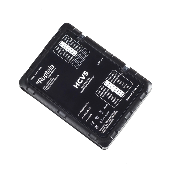
Device overview
Indication LEDs
GNSS antenna port
Audio port
14 Pin cable pinout
No.
Pin
Wire color
1
+BAT
Red
2
DOUT1
Purple
3
1W Data
Green/Yellow
4
DIN3
Pink
5
DIN4
Yellow
6
CAN2-L
Blue
7
K-Line
Brown
8
GND
Black
9
DOUT2
Orange
10
1W+5V
Red/Yellow
11
AIN2
Green
12
AIN1
Grey
13
CAN2-H
White
14
SW CAN
Green/White
www.ruptela.com
HCV5/LCV5
Quick Start Guide
Q
Device
Opening handles
16 Pin port
14 Pin port
16 Pin cable pinout
Description
Power supply (9-
32 V)
Digital output 1
1-Wire data
Digital input 3
Digital input 4
CAN Low
K-Line
Ground
Digital output 2
1-Wire power
Analogue input 2
Analogue input 1
CAN High
Single-Wire CAN
support@ruptela.com | +370 5 2045030
Center)
Grooves for zip-ties
Micro USB port
No.
Pin
Wire color
1
PortC-485 A
White/Brown
2
PortA-RS232 TX
Green/Brown
3
PortB-RS232 TX
Pink/Green
DIN1
4
Yellow/Black
DIN2
5
Pink/Black
AIN4
6
White/Green
7
CAN1-L
Blue/Red
8
GND
Black
9
PortC-485 B
Yellow/Brown
10
PortA-RS232 RX
Blue/Yellow
11
PortB-RS232 RX
Red/Cyan
DOUT3
12
White/Purple
DOUT4
13
White/Orange
14
AIN3
White/Grey
15
CAN1-H
White/Red
16
1W+5V
Red/ Yellow
Description
RS485 line A
PortA RS232 TX
PortB RS232 TX
Digital input 1
Digital input 2
Analogue input 4
CAN Low
Ground
RS485 line B
PortA RS232 RX
PortB RS232 RX
Digital output 3
Digital output 4
Analogue input 3
CAN High
1-Wire power
1
Advertisement
Table of Contents

Subscribe to Our Youtube Channel
Related Manuals for RUPTELA HCV5


Summary of Contents for RUPTELA HCV5
- Page 1 Analogue input 2 DOUT4 White/Orange Digital output 4 AIN1 Grey Analogue input 1 AIN3 White/Grey Analogue input 3 CAN2-H White CAN High CAN1-H White/Red CAN High SW CAN Green/White Single-Wire CAN 1W+5V Red/ Yellow 1-Wire power www.ruptela.com support@ruptela.com | +370 5 2045030...
- Page 2 Download and launch the Device Center. one side down until you hear a click. Push down the Install device drivers if prompted. other side until you hear a click. Click Configure device in the main menu. www.ruptela.com support@ruptela.com | +370 5 2045030...
- Page 3 Open the Connection settings. Configure Fleet Management System Main Server settings (TrustTrack server settings are entered by default). Configure GSM provider APN settings. Click Save to device to upload the config to the device. www.ruptela.com support@ruptela.com | +370 5 2045030...
- Page 4 Turn on the ignition. Test your device using the Device Center installation assistant tool. If the Overall status is green, then the device is properly installed. Check that the required data is received before finishing the installation. www.ruptela.com support@ruptela.com | +370 5 2045030...
- Page 5 We highly recommend you read the user manual before using the device. Legal information Copyright © 2021 Ruptela. All rights reserved. Reproduction, transfer, distribution or storage of parts or all of the contents in this document in any form without the prior written permission of Ruptela is prohibited. Other products and company names mentioned in this document are trademarks or trade names of their respective owners.
Need help?
Do you have a question about the HCV5 and is the answer not in the manual?
Questions and answers