RUPTELA FM-Plug4 User Manual
For more information, please visit ruptela.com
Table of Contents
Advertisement
Advertisement
Table of Contents

Related Manuals for RUPTELA FM-Plug4


Summary of Contents for RUPTELA FM-Plug4
-
Page 2: Table Of Contents
Table of contents Preface ........................... 2 Use of this document ......................2 Document change log ....................... 2 Introduction ..........................3 Purpose ........................... 3 Acronyms ......................... 3 Legal Information ......................3 Safety ..........................3 Battery handling safety ..................... 4 References ........................4 Device description ........................ -
Page 3: Preface
1 Preface 1.1 Use of this document This document provides required information for proper device handling, preparation, configuration and installation to a vehicle. This document has a linear structure – from the device package box reception to the recommendations on how to install the device to the vehicle. However it is not overfilled with unnecessary information. -
Page 4: Introduction
Copyright © 2017 Ruptela. All rights reserved. Reproduction, transfer, distribution or storage of parts or all of the contents in this document in any form without the prior written permission of Ruptela is prohibited. Other products and company names mentioned in this document are trademarks or trade names of their respective owners. -
Page 5: Battery Handling Safety
The product must be taken to separate collection points at the product`s end-of life. This chapter contains procedures to help you safely operate the FM-Plug4/4+ terminal. By following these requirements and recommendations, you will avoid dangerous situations. You must read these instructions carefully and follow them strictly before operating the device! The terminal is supplied from a car battery with these ratings: 12/24 V DC. - Page 6 FM-Plug4/4+ Datasheet – Contains technical data of the FM-Plug4/4+ device. Can be acquired from support@ruptela.com Quick start guide – A quick guide for a better understanding of the device configuration process and functions. Peripheral accessories – Instructions on how to use peripheral accessories together with the FM- Plug4/4+ device.
-
Page 7: Device Description
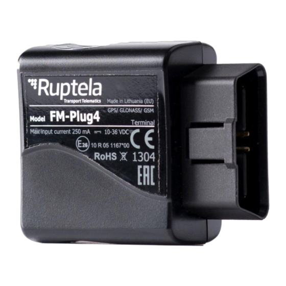
FM tracking device with easy pluggable OBD connector. It acquires its position by a GPS/GLONASS signal and transfers data to a server via a GPRS cellular network. The FM-Plug4/4+ device features: Low power consumption... -
Page 8: Technical Characteristics
Short circuit protection Reverse polarity protection Electrostatic discharge protection on USB Electrostatic discharge protection on sim card slot Charging protection (on FM-Plug4+) Currently parameter values only theoretical. FM-Plug4+ only. Currently parameter values are only theoretical. If temp is >45C, charging is disabled, if >60C battery is disconnected from the system at all... -
Page 9: Inputs/Outputs And Obd2 Pin Out
Pin function depends on vehicle manufacturer. 3.6 Peripheral accessories There are several peripheral accessories that can be mounted with the FM-Plug4/4+ device. With these peripherals you can get even more features and extended functionality. All available peripherals can be purchased from Ruptela. Please contact your manager for details. -
Page 10: Led When Gnss Fix Is Not Acquired
When device acquires a good GSM signal and is connected to GPRS, then the LED is blinking as follows: When the FM-Plug4/4+ terminal acquires a GSM signal and is sending data via GPRS, the LED is on while sending data: 3.8.2 LED when GNSS fix is not acquired... -
Page 11: Device Preparation
FM-Plug4/4+ PCB is made out of 3 smaller PCB’s parts. The main PCB with the OBD connector is at the bottom. PCB with the GSM modem and antenna is at the top. PCB with the GPS/GLONASS module and see figure below antenna is on the left side. -
Page 12: Inserting A Sim Card
Note It is recommended to keep the number of opening procedures to the minimum. 4.2 Inserting a SIM card If you received a device without a SIM card, place your own SIM card into the device as shown in the picture below. -
Page 13: Device Configuration
5 Device configuration 5.1 Driver installation Virtual COM port driver installation is mandatory, only then your PC will recognize the FM-Eco4 light device that was connected to the USB port. You can download the latest driver from our documentation website server (VCOM drivers). - Page 14 In the next window select “Next” [4.]. Wait for the setup to complete the installation and click “Finish” [5.]. Driver is now installed and ready to use.
-
Page 15: Sample Configuration
5.2 Sample configuration Go to our documentation website server and download sample configuration and the latest configurator. Also you will need the latest version of Microsoft Framework. Operating system requirements: MS Windows XP/Vista/7/8/10 Start VCP.exe from configurator folder. 1. Select Plug4 2. - Page 16 Enter APN settings: APN name, User login and Password (if login and password needed). Select a COM port you connected the device to and click Connect. At this point the configuration is ready to be send to the device, so the device must be connected to the computer. Click Send CFG button.
-
Page 17: Advanced Configuration
5.3 Advanced configuration The configuration tool is quite similar to the ones used for other 4 generation devices. Overview of the configuration is described in sections. “File” menu gives you access to control New/Save/Open CFG configuration files. Choose perform the corresponding action. CFG means full configuration file. -
Page 18: Global Settings
5.3.1 Global settings The first part of the configuration tool is “Global” settings. Global include connection settings and other settings independent from the profile settings – global settings are the same for all profiles. Connection settings here you should enter server IP and port that the device should connect to. The IP can be entered in the numeric format: 255.255.255.255. - Page 19 Send data without GPS fix – This function is limited to the GSM tracking function. The “Send data without GPS fix” function is disabled for the FM-Plug4 device. When the device loses GPS fix, there is no way to determine its location. GSM tracking feature can now be used to obtain an approximate location in the densely urbanized areas, where GPS signal is not available.
-
Page 20: Profile Settings
Movement sensor sensitivity allows you to configure movement sensor according to your needs. If you slide the bar towards the Max, the sensor will detect even very slight movements. If you slide it to the Min, than only stronger movements will be detected. Send identification string feature forces FM device to send an identification packet to the server. - Page 21 voltage level at the OBD2 Pin 16 will drop to zero and the device will shut down immediately. (In some older vehicle models the voltage level at the OBD Pin 16 drops below 13 V, but not to 0 V. In such cases the device will enter the Deep sleep mode, after a certain amount of time have passed, usually this takes 10 minutes).
- Page 22 Data collection must be enabled to collect the information. Time without engine means how often records should be made, when the engine is off. Engine drop box allows you to choose how the device will pick up the ignition (consider that the engine is on).
- Page 23 Device is configured to track one event for 1h. However actual event tracking might last for 1h ± Error (i.e. 5 seconds). Device is configured to gather records every second. Depending on the device’s state, record gathering time might deviate and last longer (i.e. 2, 3 or even 5 seconds). Operator list …...
- Page 24 Received trouble codes can be monitored with the help of "GSM trouble codes" IO parameter. Note This functionality might be compatible and might be supported with 3G modems used in Ruptela's FM devices. Key point about the temporary black list: Ban period is configurable.
-
Page 25: Io Settings
5.3.3 IO settings IO events “Options” buttons opens up a new “IO settings” window, here you can enable or disable IO parameters that will be sent to a server. The setting the user should configure, is the protocol selection. Protocol selection section has a checkbox, where you can choose to “Send I/O data with v1.1 protocol”. - Page 26 Note Some IOs will have a "Debounce" setting instead of the "Average" setting. Debounce defines for how long the device must receive a changed state of an IO, before it registers the changed state. For example, the DIN state changed from 0 to 1 and Debounce is set to 5000ms, so the signal from the DIN must remain constant for the period of 5000ms to actually change the state of the IO from 0 to 1.
- Page 27 The next method describes how to automatically enable and configure commonly used IOs. To do this, the user must simply click the “Enable common IO” button. This will open a window with a list of IO parameters that will be enabled along with additional information, such as: Free IO slots remaining after the selected IOs are enabled;...
-
Page 28: Integration Protocol
DTC enable - here you can specify Diagnostic Trouble Codes reading interval in minutes. Below “Gasoline”, “Diesel”. two additional checkboxes are displayed, meant to specify Fuel type: More information available at our on our documentation website. 5.4 Integration protocol All integration related questions and documentation can be acquired from Ruptela technical support: support@ruptela.com... -
Page 29: Device Installation
6 Device installation Locate OBD2 socket in your vehicle. Insert FM-Plug4 / FM-Plug4+ device into OBD2 socket as showed in the picture below. There is only one way to plug the device, be careful not to damage the pins.
Need help?
Do you have a question about the FM-Plug4 and is the answer not in the manual?
Questions and answers