
Related Manuals for DFI AL9A2


Summary of Contents for DFI AL9A2
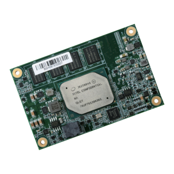
- Page 1 AL9A2 COM Express Mini Module User’s Manual A46200902 Chapter 1 Introduction www.dfi .com...
-
Page 2: Copyright
Copyright FCC and DOC Statement on Class B This publication contains information that is protected by copyright. No part of it may be re- This equipment has been tested and found to comply with the limits for a Class B digital produced in any form or by any means or used to make any transformation/adaptation without device, pursuant to Part 15 of the FCC rules. -
Page 3: Table Of Contents
COM Express Connector ................12 COM Express Connector Signal Discription ........... 15 Cooling Option .................... 21 Heat Sink ....................21 Installing AL9A2 onto a Carrier Board ..........21 Installing the COM Express Debug Card ..........22 Chapter 1 Introduction www.dfi .com... -
Page 4: Warranty
Warranty Static Electricity Precautions 1. Warranty does not cover damages or failures that arised from misuse of the product, It is quite easy to inadvertently damage your PC, system board, components or devices even inability to use the product, unauthorized replacement or alteration of components and before installing them in your system unit. -
Page 5: About The Package
About the Package The package contains the following items. If any of these items are missing or damaged, please contact your dealer or sales representative for assistance. • 1 AL9A2 board • 1 Heat sink Optional Items • COM100-B carrier board kit •... -
Page 6: Chapter 1 - Introduction
Chapter 1 Chapter 1 - Introduction Specifications SYSTEM Processor Intel Atom ® Processor E3900 Series, BGA 1296 WATCHDOG Output & System Reset, Programmable via Software from 1 to 255 Seconds TIMER ® Intel Atom x7-E3950 Processor, Quad Core, 2M Cache, 1.6GHz (2.0GHz), 12W Interval ®... -
Page 7: Features
Chapter 1 Features • Watchdog Timer The Watchdog Timer function allows your application to regularly “clear” the system at the set time interval. If the system hangs or fails to function, it will reset at the set time interval so that your system will continue to operate. -
Page 8: Chapter 2 - Concept
Chapter 2 - Concept COM Express Module Standards The figure below shows the dimensions of the different types of COM Express modules. AL9A2 is a COM Express Mini. The dimension is 84mm x 55mm. Common for all Form Factors Extended only... -
Page 9: Specification Comparison Table
Chapter 2 Specification Comparison Table The table below shows the COM Express standard specifications and the corresponding specifications supported on the AL9A2 module. COM Express Module Base COM Express Module Base Specification Type 10 Specification Type 10 DFI AL9A2 DFI AL9A2... -
Page 10: Chapter 3 - Hardware Installation
Chapter 3 Chapter 3 - Hardware Installation Block Diagram Board Layout PCIe x1 ® Intel I210AT ® Intel I210IT SATA 3.0 2x SATA 3.0 2x MMC Bus eMMC (Optional) LPC Bus LPC Bus Intel Atom SLP/LID 8GB DDR3L Memory Down Fan PWM/ Channel A (ECC support) -
Page 11: System Memory
Chapter 3 Important: System Memory Electrostatic discharge (ESD) can damage your board, processor, disk drives, add-in DDR3L boards, and other components. Perform installation procedures at an ESD workstation only. If such a station is not available, you can provide some ESD protection by wear- ing an antistatic wrist strap and attaching it to a metal part of the system chassis. -
Page 12: Connectors
Connectors COM Express Connector The COM Express connector is used to interface the AL9A2 COM Express board to a carrier board. Connect the COM Express connector (located on the solder side of the board) to the COM Express connector on the carrier board. - Page 13 Chapter 3 COM Express Connector Row A Row B Row A Row B AC/HDA_BITCLK / 3.3V Suspend SPKR GBE_MDI3- GBE_ACT# / 3.3V Suspend AC/HDA_SDOUT / 3.3V Suspend I2C_CK / 3.3V Suspend GBE_MDI3+ LPC_FRAME# BIOS_DIS0# I2C_DAT / 3.3V Suspend GBE_LED_100- / 3.3V Suspend LPC_AD0 THRMTRIP# / 3.3V Suspend THRM#...
- Page 14 Chapter 3 Row A Row B Row A Row B SPI_POWER / 3.3V Suspend PCIE_TX2+ PCIE_RX2+ SPI_MISO / 3.3V Suspend PCIE_TX2- PCIE_RX2- GPO0 GPI1 GPO3 SPI_CLK / 3.3V Suspend PCIE_TX1+ PCIE_RX1+ SPI_MOSI / 3.3V Suspend DDI0_DDC_AUX_SEL PCIE_TX1- PCIE_RX1- NC / USB_HOST_PRSNT 3.3V (option) WAKE0# TYPE10# / Pull down 47k ohm to GND SPI_CS# / 3.3V Suspend...
-
Page 15: Com Express Connector Signal Discription
I/O Bi-directional input / output signal OD Open drain output AC97/HDA Signals Descriptions Signal Pin# Pin Type Pwr Rail /Tolerance AL9A2 Carrier Board Description AC/HDA_RST# O CMOS 3.3V Suspend/3.3V Connect to CODEC pin 11 RESET# Reset output to CODEC, active low. - Page 16 O PCIE AC coupled off Module DDI 0 Pair 3 differential pairs/Serial Digital Video B clock output differential pair. DDI0_PAIR3-/DP0_LANE3- Connect AC Coupling Capacitors 0.1uF to Device DDI0_PAIR4+ NA for AL9A2 DDI0_PAIR4- DDI0_PAIR5+ NA for AL9A2 DDI0_PAIR5- DDI0_PAIR6+ NA for AL9A2...
- Page 17 DDI[n]_AUX pair as the DDC channel. Carrier DDI[n]_DDC_AUX_SEL should be connected to pin 13 of the DisplayPort USB Signals Descriptions Signal Pin# Pin Type Pwr Rail /Tolerance AL9A2 Carrier Board Description USB0+ Connect 90 @100MHz Common Choke in series I/O USB 3.3V Suspend/3.3V...
- Page 18 Additional receive signal differential pairs for the SuperSpeed USB data path. and ESD suppressors to GND to USB connector USB_SSRX1- Module USB client may detect the presence of a USB host. A high value (NA for AL9A2) USB_HOST_PRSNT I CMOS 3.3V Suspend/3.3V...
- Page 19 TPM chip has an internal pull down. This signal is used to indicate TPM_PP I CMOS 3.3V / 3.3V Physical Presence to the TPM. (NC for AL9A2) Power and System Management Signals Descriptions Signal Pin# Pin Type Pwr Rail /Tolerance...
- Page 20 PU 10K to 3.3VSB generate an SMI# (System Management Interrupt) or to wake the system. GPIO Signals Descriptions Signal Pin# Pin Type Pwr Rail /Tolerance AL9A2 Carrier Board Description GPO0 GPO1 O CMOS 3.3V / 3.3V General purpose output pins.
-
Page 21: Cooling Option
AL9A2 onto the carrier board of your choice. 1. Grasp AL9A2 by its edges and position it on top of the carrier board with its COM Express connector aligned with the COM Express connector on the carrier board. This will also help align the mountings holes of AL9A2 with the standoffs on the carrier board. -
Page 22: Installing The Com Express Debug Card
The system board used in the following illustrations may not resemble the actual board. These illustrations are for reference only. 1. COMe-LINK2 is the COM Express debug platform installed into COM Express Mini modules for the application of debugging and displaying signals and codes. AL9A2 Carrier board COM Express Connector 3. - Page 23 Chapter 3 2. Connect the COMe-DEBUG card to COMe-LINK2 via a cable. 3. Fasten bolts with mounting screws through mounting holes to be fixed in place. COMe-DEBUG Code Review 80 Port Display Control Mounting screws COMe-LINK1/2 Connector COM Express COM Express Type Display Signal Display COM Express...
- Page 24 Chapter 3 5. Grasp the COM Express Mini module by its edges to press it down on the top of the 7. Use the long mounting screws to secure the heat sink on the top of the COM Express Mini COMe-LINK2 debug card.
-
Page 25: Chapter 4 - Bios Setup
Chapter 4 Chapter 4 - BIOS Setup Legends Overview KEYs Function The BIOS is a program that takes care of the basic level of communication between the CPU Right and Left Arrows Moves the highlight left or right to select a and peripherals. -
Page 26: Ami Bios Setup Utility
Aptio Setup Utility - Copyright (C) 2018 American Megatrends, Inc. Setting incorrect field values may cause the system to malfunction. Main Advanced Security Boot Save & Exit Project Name AL9A2 Set the Time. Use Tab BIOS Version B18B.14A to switch between Time EC Version 2018.09.04 v0.2 elements. - Page 27 Chapter 4 ACPI Configuration Note: If Quiet Boot is set to enabled, BGRT Logo field will appear for configuration. Refer This section is used to configure ACPI settings. to the Boot menu for more information. Aptio Setup Utility - Copyright (C) 2018 American Megatrends, Inc. Advanced Aptio Setup Utility - Copyright (C) 2018 American Megatrends, Inc.
- Page 28 Chapter 4 CPU Configuration Video Configuration This section is used to configure the CPU. This section configures the video settings. Aptio Setup Utility - Copyright (C) 2018 American Megatrends, Inc. Aptio Setup Utility - Copyright (C) 2018 American Megatrends, Inc. Advanced Advanced EIST...
- Page 29 Chapter 4 Audio Configuration SATA Configuration This section configures the audio settings. This section configures the SATA controller. Aptio Setup Utility - Copyright (C) 2018 American Megatrends, Inc. Aptio Setup Utility - Copyright (C) 2018 American Megatrends, Inc. Advanced Advanced Enable/Disable HD-Audio Enables or Disables Audio Controller...
- Page 30 Chapter 4 PCI Express Configuration Aptio Setup Utility - Copyright (C) 2018 American Megatrends, Inc. Advanced This section configues settings relevant to PCI Express devices. Control the PCI Express PCI Express Root Port 3 [Enable] Hot Plug [Disable] Root Port. Enable: Enable PCIe PCIe Speed [Auto]...
- Page 31 Chapter 4 Console Redirection Aptio Setup Utility - Copyright (C) 2018 American Megatrends, Inc. Advanced This section configures settings relevant to console redirection. COM1 Emulation: ANSI: Console Redirection Settings Extended ASCII char set. VT100: ASCII char set. Aptio Setup Utility - Copyright (C) 2018 American Megatrends, Inc. Terminal Type [VT100+] VT100+: Extends VT100...
- Page 32 Chapter 4 PC Health Status WatchDog Configuration This section only displays the hardware health monitor. This section is used to configure WatchDog parameters. Aptio Setup Utility - Copyright (C) 2018 American Megatrends, Inc. Aptio Setup Utility - Copyright (C) 2018 American Megatrends, Inc. Advanced Advanced Enable/Disable Watch-...
-
Page 33: Security
Chapter 4 Security IT8528 Super IO Configuration This section configures the system super I/O chip parameters. Aptio Setup Utility - Copyright (C) 2018 American Megatrends, Inc. Aptio Setup Utility - Copyright (C) 2018 American Megatrends, Inc. Save & Exit Main Advanced Security Boot... -
Page 34: Boot
Chapter 4 Boot Aptio Setup Utility - Copyright (C) 2018 American Megatrends, Inc. Security TPM20 Device Found Enables or Disables BIOS support for security Vendor: INTC Aptio Setup Utility - Copyright (C) 2018 American Megatrends, Inc. Firmware Version: 3.1 device. O.S. will not show Security Device. -
Page 35: Save & Exit
Select Yes and then press <Enter> to exit the system setup without saving your changes. Sets the system boot order. Driver Option Priorities Sets the driver boot order. Note: AL9A2 only supports UEFI boot, no Legacy boot. Chapter 4 BIOS Setup www.dfi .com... -
Page 36: Updating The Bios
For updating AMI BIOS in UEFI mode, Due to the safety concerns, the BIOS (SPI ROM) chip cannot be removed from this system you may refer to the how-to-video at https://www.dfi.com/Knowledge/Video/5 . board and used on another system board of the same model. -
Page 37: Chapter 5 - Supported Software
® INF files so that the Intel chipset can be recognized and configured properly in the system. To install the utility, download “AL9A2 Chipset Driver” zip file at our website. 1. Setup is ready to install the utility. Click “Next”. - Page 38 Chapter 5 Intel Graphics Driver 3. Go through the readme document for system re- To install the driver, download “AL9A2 Graphics Driver” zip file at our website. quirements and installation tips then click “Next”. 1. Setup is now ready to install the graphics driver.
- Page 39 Chapter 5 Audio Drivers Intel LAN Driver To install the driver, download “AL9A2 Audio Driver” zip file at our website. To install the driver, download “AL9A2 LAN Driver” zip file at our website. 1. Setup is ready to install the 1.
- Page 40 Chapter 5 4. Click “Install” to begin the 6. After completing installa- installation. tion, click “Finish”. 5. The step displays the installing status in the prog- ress. Chapter 5 Supported Software www.dfi .com...
- Page 41 Intel Trusted Execution Engine Driver 3. The step displays the installing status in the progress. To install the driver, download “AL9A2 TXE Driver” zip file at our website. 1. Tick “I accept the terms in the License Agreement” and then click “Next”.
- Page 42 SIO Driver 3. Read the file information then click “Next”. To install the driver, download “AL9A2 SIO Driver” zip file at our website. 1. Setup is ready to install the driver. Click “Next”. 4. Setup is ready to install the driver.
- Page 43 Chapter 5 5. Setup is now installing the driver. 6. Click “Finish”. Chapter 5 Supported Software www.dfi .com...
-
Page 44: Chapter 6 - Gpio Programming Code
Chapter 6 Chapter 6 - GPIO Programming Guide Function Description Get_EC_Data (unsigned char ucData): Read a Byte data from EC. Write_EC_Data (unsigned char ucData, unsigned char Data): Write a Byte data to EC. Sample Code GPIO Input Process EC_DIO_Read_Input() BYTE Data; //Pin0-3 Input Mode Data = Get_EC_Data(0xBA);... -
Page 45: Appendix A - Watchdog Sample Code
Appendix A Appendix A - Watchdog Sample Code #include <stdio.h> int GetWDTime(void) //-------------------------------------------------------------- #defi ne EC_EnablePort 0x66 int sum,data_h,data_l; #defi ne EC_DataPort 0x62 //Select EC Read Type //-------------------------------------------------------------- outportb(EC_EnablePort,0x80); void WriteEC(char,int); delay(5); void SetWDTime(int,int); //Get Remaining Count High Byte int GetWDTime(void); outportb(EC_DataPort,0xF4);... -
Page 46: Appendix B - System Error Message
Appendix B Appendix B - System Error Message DXE Phase Codes Standard Status Codes PEI Status Codes PEI Error Codes DXE Error Codes Appendix B System Error Message www.dfi .com... - Page 47 Appendix B ACPI Checkpoints Beep Code Appendix B System Error Message www.dfi .com...
-
Page 48: Appendix C - Troubleshooting
Appendix C Appendix C - Troubleshooting The picture seems to be constantly moving. 1. The monitor has lost its vertical sync. Adjust the monitor’s vertical sync. Troubleshooting Checklist 2. Move away any objects, such as another monitor or fan, that may be creating a magnetic This chapter of the manual is designed to help you with problems that you may encounter field around the display. - Page 49 Appendix C Hard Drive System Board 1. Make sure the add-in card is seated securely in the expansion slot. If the add-in card is Hard disk failure. loose, power off the system, re-install the card and power up the system. 1.
Need help?
Do you have a question about the AL9A2 and is the answer not in the manual?
Questions and answers