
Related Manuals for DFI AD76 RAID


Summary of Contents for DFI AD76 RAID
- Page 1 AD76 RAID Rev. A+ System Board User’s Manual Carte Mère Manuel Pour Utilisateur System-Platine Benutzerhandbuch Manual del Usuario de Placas Base 935-AD7601-000 59700225...
- Page 2 Copyright This publication contains information that is protected by copyright. No part of it may be reproduced in any form or by any means or used to make any transformation/adaptation without the prior written permission from the copyright holders. This publication is provided for informational purposes only. The manufacturer makes no representations or warranties with respect to the contents or use of this manual and specifically disclaims any express or implied warranties of merchantability or fitness for any...
- Page 3 Battery: • Danger of explosion if battery incorrectly replaced. • Replace only with the same or equivalent type recommend by the manufacturer. • Dispose of used batteries according to the batter y manufacturer’s instructions. Joystick or MIDI port: • Do not use any joystick or MIDI device that requires more than 10A current at 5V DC.
- Page 4 Quick Setup Guide Table of Contents Chapter 1 Quick Setup Guide..........Chapter 2 English..............Chapter 3 Français (French)..........Chapter 4 Deutsch (German)..........Chapter 5 Español (Spanish)..........Note: The user’s manual in the provided CD contains detailed information about the system board. If, in some cases, some information doesn’t match those shown in this manual, this manual should always be regarded as the most updated version.
- Page 5 Quick Setup Guide Chapter 1 - Quick Setup Guide Table of Contents 1.1 System Board Layout....................1.2 Jumpers............................. 1.3 Ports and Connectors....................1.4 Award BIOS Setup Utility..................Important: To ensure proper boot up and operation of your system, you must power-off the system then turn off the power supply’s switch or unplug the AC power cord prior to altering the setting of a jumper or replacing the CPU.
-
Page 6: System Board Layout
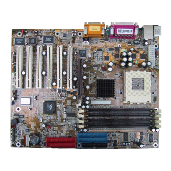
Quick Setup Guide 1.1 System Board Layout PS/2 KB/Mouse power select (JP1) DIMM standby CPU fan (J18) power LED J2 ATX power (J19) COM 1 (J3) Secondary IDE (J29) Parallel (J4) Primary IDE (J27) (J34) Chassis fan (J21) COM 2 (J5) KT333 Line (J6) -
Page 7: Jumpers
Quick Setup Guide 1.2 Jumpers 1.2.1 Clear CMOS Data - JP5 1-2 On: Normal (default) 2-3 On: Clear CMOS Data Clear CMOS 1 2 3 (JP5) 1.2.2 CPU’s Front Side Bus - JP4 100MHz (200MHz FSB) (default) Off: CPU FSB select (JP4) 133MHz (266MHz FSB) To ensure proper boot up and operation of your system, you must power-... - Page 8 Quick Setup Guide 1.2.3 Power Select for PS/2 (JP1) PS/2 KB/Mouse power select (JP1) 1-2 On: 5V (default) 2-3 On: 5VSB 1.2.4 Wake-On-USB 2.0 Keyboard/Mouse - J11 1-2 On: Enable - 5VSB power (default) 2-3 On: Disable - VCC power 1 2 3 Wake-On-USB 2.0 KB/Mouse (J11)
- Page 9 Quick Setup Guide 1.2.5 RAID Settings - JP2 1-2 On: Disable the RAID function 2-3 On: Enable the RAID function (default) 1 2 3 RAID setting (JP2)
-
Page 10: Ports And Connectors
Quick Setup Guide 1.3 Ports and Connectors 1.3.1 PS/2 Mouse and PS/2 Keyboard Ports PS/2 Mouse PS/2 Keyboard Make sure to turn off your computer prior to connecting or disconnecting a mouse or keyboard. Failure to do so may damage the system board. - Page 11 Quick Setup Guide 1.3.3 Universal Serial Bus Ports USB 2.0 (J20 and J22) 5V_Dul 6 Data+ 5V_Dul 7 Ground Data- 8 Ground Data- 9 Key Data+ 10 Ground USB 1.1 (J25) 1 VCC 9 Ground UP2- 10 Ground UP2+ 11 Ground USB 2.0 Ground 12 Gound...
- Page 12 Quick Setup Guide 1.3.5 Parallel Port Parallel Port Parallel (Burgundy) 1.3.6 Game/MIDI Port and Audio Jacks Onboard Game/MIDI / Audio Game/MIDI Port Audio Jacks Line-out Line-in Mic-in Front Audio (J13) Mic+ Ground Mic Power AuD_Vcc (Avcc) AuD_R_Out AuD_R_Return (GND) N. C. AuD_L_Out 1 0 AuD_L_Return (GND)
- Page 13 Quick Setup Guide 1.3.7 S/PDIF-out Connector AVDD5 N. C. SPDIF S/PDIF-out (J38) 1 2 3 4 Ground 1.3.8 Internal Audio Connectors CD-in (J12) Left audio channel Ground AUX-in (J15) Ground Right audio channel...
- Page 14 Quick Setup Guide 1.3.9 Floppy Disk Drive and IDE Disk Drive Connectors FDD (J34) Primary IDE (J27) Secondary IDE (J29) If you encountered problems while using an ATAPI CD-ROM drive that is set in Master mode, please set the CD-ROM drive to Slave mode. Some ATAPI CD-ROMs may not be recognized and cannot be used if incorrectly set in Master mode.
- Page 15 Quick Setup Guide 1.3.10 RAID IDE Disk Drive Connectors RAID Primary IDE (J31) RAID Secondary IDE (J35) Only connect IDE hard drives to the RAID IDE connectors. PCI slot 3 and RAID IDE use the same IRQ. If you are using add-in cards such as PCI audio card, please do not install it into PCI slot 3.
- Page 16 Quick Setup Guide 1.3.11 IrDA Connector 1 VCC 2 N. C. 3 IRRX 4 Ground 5 IRTX IrDA (J17) 1 2 3 4 5 The sequence of the pin functions on some IrDA cable may be reversed from the pin function defined on the system board. Make sure to connect the cable to the IrDA connector according to their pin functions.
- Page 17 Quick Setup Guide 1.3.12 Fan Connectors CPU fan (J18) CPU Fan 1 On 2 +12V Chassis 3 Sense fan (J21) Chassis Fan 1 On/Off 2 +12V 3 Sense Second Chassis Fan 1 Ground Second Chassis fan 2 +12V (J26) 3 N. C. 1.3.13 Wake-On-LAN Connector 1 +5VSB 2 Ground...
- Page 18 Quick Setup Guide 1.3.14 Wake-On-Ring Connector 1 Ground 2 RI# If you are using a modem add-in card, the 5VSB power source of your power supply must support ≥720mA. Wake-On-Ring (J24) 1.3.15 Power Connector ATX power 3.3V 1 1 3.3V (J19) 3.3V 1 2 -12V...
- Page 19 Quick Setup Guide 1.3.16 DIMM and PCI Standby Power LEDs DIMM standby power LED PCI standby power LED DIMM Standby Power LED This LED will turn red when the system’s power is on or when it is in the Suspend state (Power On Suspend or Suspend to RAM). It will not light when the system is in the Soft-Off state.
- Page 20 Quick Setup Guide 1.3.17 Front Panel Connectors HD-LED SPEAKER RESET Front panel G-LED PWR-LED connectors (J28) G-SW ATX-SW Pin Assignment HD-LED HDD LED Power (Primary/Secondary IDE LED) G-LED Green LED Power (Green LED) Ground ATX-SW PWRBT+ (ATX power switch) PWRBT- G-SW Ground (Green switch)
-
Page 21: Award Bios Setup Utility
Quick Setup Guide 1.4 Award BIOS Setup Utility 1.4.1 Main Menu CMOS Setup Utility - Copyright (C) 1984-2000 Award Software Standard CMOS Features Frequency/Voltage Control Load Fail-Safe Defaults Advanced BIOS Features Advanced Chipset Features Load Optimized Defaults Integrated Peripherals Set Supervisor Password Set User Password Power Management Setup PnP/PCI Configurations... - Page 22 Quick Setup Guide 1.4.3 Advanced BIOS Features CMOS Setup Utility - Copyright (C) 1984-2000 Award Software Advanced BIOS Features Item Help Promise RAID Control Enabled Virus Warning Disabled Menu Level CPU L1 Cache Enabled CPU L2 Cache Enabled Allows you to choose CPU L2 Cache ECC Checking Enabled the VIRUS warning...
- Page 23 Quick Setup Guide 1.4.5 Integrated Peripherals CMOS Setup Utility - Copyright (C) 1984-2000 Award Software Integrated Peripherals Item Help VIA OnChip IDE Device Press Enter VIA OnChip PCI Device Press Enter Menu Level Super IO Device Press Enter Init Display First PCI Slot OnChip USB Controller All Enabled...
- Page 24 Quick Setup Guide 1.4.7 PnP/PCI Configurations CMOS Setup Utility - Copyright (C) 1984-2000 Award Software PnP/PCI Configurations Item Help Reset Configuration Data Disabled Menu Level Resources Controlled By Auto(ESCD) IRQ Resources Press Enter Default is Disabled. Select Enabled to PCI/VGA Palette Snoop Disabled reset Extended System Configuration Data...
- Page 25 Quick Setup Guide 1.4.9 Frequency/Voltage Control CMOS Setup Utility - Copyright (C) 1984-2000 Award Software Frequency/Voltage Control Item Help DRAM Voltage Adjust 2.50V Auto Detect DIMM/PCI Clk Enabled Menu Level Spread Spectrum Modulated Disabled Clock By Slight Adjust AGP Voltage Adjust 1.50V Chipset Voltage Adjust 2.50V...
-
Page 26: Table Of Contents
English Chapter 2 - English Table of Contents 2.1 Features and Specifications..................2.2 Using the CPU Fan Protection Function........... 2.3 Using the Suspend to RAM Function............2.4 Supported Softwares....................2.5 Troubleshooting......................... Package Checklist The system board package contains the following items: The system board A user’s manual Two IDE cables for ATA/33, ATA/66, ATA/100 or ATA/133 IDE... -
Page 27: Features And Specifications
English 2.1 Features and Specifications 2.1.1 Features Chipset ® • VIA KT-333 and VT8233ACE Processor The system board is equipped with Socket A for 462-pin PGA processor. It is also equipped with a switching voltage regulator that automatically detects 1.100V to 1.850V. •... - Page 28 English Expansion Slots The system board is equipped with 1 universal AGP slot and 6 PCI slots. AGP is an interface designed to support high performance 3D graphics cards. It utilizes a dedicated pipeline to access system memory for texturing, z-buffering and alpha blending. The universal AGP slot supports AGP 2x with up to 533MB/sec.
- Page 29 English Connectors Two connector for 4 additional external USB 2.0 ports - One connector for 2 additional external USB 1.1 ports - One connector for external line-out annd mic-in jacks - Two internal audio connectors (AUX-in and CD-in) - One S/PDIF-out connector One connector for IrDA interface Two RAID IDE connectors Two IDE connectors...
- Page 30 English USB Ports The system board supports USB 2.0 and USB 1.1 ports. USB 1.1 supports 12Mb/second bandwidth while USB 2.0 supports 480Mb/ second bandwidth providing a marked improvement in device transfer speeds between your computer and a wide range of simultaneously accessible external Plug and Play peripherals.
- Page 31 English 2.1.3 Intelligence BitGuard BitGuard is designed to keep a watch over the entire system and take out any problems before they develop. It will look after the AMD Athlon XP CPU by working with the Thermal Diode of the CPU and will shut the system down anytime the CPU gets too hot.
- Page 32 English Automatic Chassis Fan Off The chassis fan will automatically turn off once the system enters the Suspend mode. Dual Function Power Button Depending on the setting in the “Soft-Off By PWRBTN” field of the Power Management Setup, this switch will allow the system to enter the Soft-Off or Suspend mode.
- Page 33 English The system board is designed to meet the ACPI (Advanced Configuration and Power Interface) specification. ACPI has energy saving features that enables PCs to implement Power Management and Plug-and-Play with operating systems that support OS Direct ® ® ® ® ® Power Management.
-
Page 34: Using The Cpu Fan Protection Function
English 2.2 Using the CPU Fan Protection Function The CPU must be kept cool by using a CPU fan with heatsink. Without sufficient air circulation across the CPU and heatsink, the CPU will overheat damaging both the CPU and system board. The CPU Fan Protection function supported by the system board has the capability of monitoring the CPU fan during system boot-up and will automatically power-off the system once it has detected that... -
Page 35: Using The Suspend To Ram Function
English restart the system. If the same problem occurs, you must replace it with a good quality fan - one that will rotate immediately once power comes in and also one that can dissipate heat more efficiently, otherwise, you have to disable this function in the “CPU Fan Protection”... - Page 36 English Click File System. In the “Typical role of this computer” field, select “Mobile or docking system”. Click Apply, then click OK. Restart the computer. 10. Repeat step 7 to open the Control Panel dialog box. Double- click the Power Management icon. 11.
-
Page 37: Supported Softwares
English 2.4 Supported Softwares The CD that came with the system board contains drivers, utilities and software applications required to enhance the performance of the system board. Insert the CD into a CD-ROM drive. The autorun screen (Main Board Utility CD) will appear. If after inserting the CD, "Autorun" did not automatically start (which is, the Main Board Utility CD screen did not appear), please go directly to the root directory of the CD and double-click "Setup". - Page 38 English • AGP VxD Driver • IRQ Routing Miniport Driver • VIA INF Driver To install VIA Service Pack, please follow the steps below. 1. Click “VIA Service Pack”. The “Welcome” screen will appear. 2. Click “Next”. Please read the “VIA Service Pack Readme” carefully before proceeding to step 3.
- Page 39 English 2.. Follow the prompts on the screen to complete installation. 3. Reboot the system for the driver to take effect. 2.4.4 Realtek LAN Drivers The LAN drivers for Windows ME, Windows 2000 and Windows XP support “Autorun”. To install the Realtek LAN driver, please follow the steps below.
- Page 40 Board Utility CD screen did not appear), please go directly to the root directory of the CD and double-click "Setup". 2. Please go to DFI's web site at "http://www.dfi.com/support1/ download2.asp" for the latest version of the drivers or software applications.
-
Page 41: Troubleshooting
English 2.5 Troubleshooting This section of the manual is designed to help you with problems that you may encounter with your personal computer. To efficiently troubleshoot your system, treat each problem individually. This is to ensure an accurate diagnosis of the problem in case a problem has multiple causes. - Page 42 English Monitor/Display If the display screen remains dark after the system is turned on: 1. Make sure that the monitor’s power switch is on. 2. Check that one end of the monitor’s power cord is properly attached to the monitor and the other end is plugged into a working AC outlet.
- Page 43 English Floppy Drive The computer cannot access the floppy drive. 1. The floppy diskette may not be formatted. Format the diskette and try again. 2. The diskette may be write-protected. Use a diskette that is not write-protected. 3. You may be writing to the wrong drive. Check the path statement to make sure you are writing to the targeted drive.
- Page 44 English Parallel Port The parallel printer doesn’t respond when you try to print. 1. Make sure that your printer is turned on and that the printer is on-line. 2. Make sure your software is configured for the right type of printer attached.
- Page 45 English System Board 1. Make sure the add-in card is seated securely in the expansion slot. If the add-in card is loose, power off the system, re-install the card and power up the system. 2. Check the jumper settings to ensure that the jumpers are properly set.
- Page 46 Français (French) Chapter 3 - Français (French) Table des Matières Liste de Vérification de l’Emballage þ þ þ þ þ þ Note: Le manuel d’utilisateur dans le CD muni contient renseignement détaillé au sujet de carte de système. Si, en quelque cas, quelque renseignement n’appareille de ce que dit dans ce manuel, ce manuel doit toujours être considéré...
- Page 47 Français (French) 3.1 Caractéristiques et Spécifications 3.1.1 Caractéristiques Chipset Processeur Importance: Pour être sur que le système puisset correctement démarrer, avant changement du processeur, vous devrez éteindre la machine et débrancher la prise du courant éléctrique. Mémoire Système Mémoire DIMMs DIMMs Mémoire...
- Page 48 Français (French) Logements d’Extension Caractéristiques Audio sur Carte...
- Page 49 Français (French) Connecteurs ATA RAID - Redundant Array of Inexpensive Disk [Réseau Redondant de Disques bons marchés] Contrôleur IDE de BUS Maître PCI Interface IrDA...
- Page 50 Français (French) Ports USB BIOS Interface de Gestion de Bureau (DMI) 3.1.2 System Health Monitor Fonctions La carte système est capable de gérer les conditions de “santé système” suivantes.
- Page 51 Français (French) 3.1.3 Intelligence BitGuard Protection de Température de CPU Protection du CPU par Ventilateur Sur-Voltage...
- Page 52 Français (French) D’accélération d’horloge de CPU Arrêt Automatique de Ventilateur de Châssis Bouton d’Alimentation à Fonction Double Wake-On-Ring Importance: Si vous utilisez une carte complémentaire de modem, la source d’alimentation de 5VSB de votre boîtier d’alimentation doit supporter un minimum de ≥ 720mA. Minuterie RTC pour Allumer le Système Wake-On-LAN...
- Page 53 Français (French) Importance: La source d’alimentation 5VSB de votre boîtier d’alimentation doit supporter ≥ 720mA (minimum). Récupération après Défaillance d’Alimentation CA ACPI STR Importance: La source d’alimentation 5VSB de votre boîtier d’alimentation doit supporter ≥ 1A. Protection contre les Virus...
- Page 54 Français (French) 3.2 Utilisation de la Fonction de Protection de CPU par Ventilateur...
- Page 55 Français (French) 3.3 Utilisation de la Fonction de Suspension sur...
- Page 56 Français (French) Importance: Si vous ne pouvez pas utiliser le Suspend à la RAM fonction (après exécuter les marches ci-dessus dans Windows 2000/ ® ME/XP), veuillez verifier si votre add-in-cartes ou le périphérique qui supporte cette fonction. Si cette fonction n’est pas supportée, vous avez besoin de télécharger le driver convenable à...
- Page 57 Français (French) 3.4 Logiciels Supportés 3.4.1 Utilitaire Hardware Monitor Note: Utilisez cet utilitaire seulement dans les systèmes d’exploitation Windows 95, Windows 98, Windows 98 SE, Windows ® ® ® ® Windows 2000 ou Windows NT 4.0. ® ® 3.4.2 VIA Service Pack...
- Page 58 Français (French) Notes d’Installation de VIA Service Pack ® Importance: Le pilote VGA qui accompagne les cartes AGP est déjà groupé avec le pilote AGP VxD. Etant donné que la version du pilote groupé VxD est peut-être plus ancienne que celle fournie dans le CD, l’installation du groupe VxD peut poser des problèmes.
- Page 59 Français (French) 3.4.4 Le Pilote Realtek LAN 3.4.5 Pilotes VIA USB 2.0...
- Page 60 Français (French) 3.4.6 Pilotes Promise RAID 3.4.7 Utilitaire Promise RAID 3.4.8 Pilote de Microsoft DirectX 8.1 3.4.9 Notes pour l’Installation des Pilotes et des Utilitaires...
- Page 61 Français (French)
- Page 62 Français (French) 3.5 Dépannage Protection CPU par Ventilateur Après avoir amorcé le système, une alarme sonore retentit puis l’alimentation du système est mise hors tension.
- Page 63 Français (French) Moniteur/Affichage Si l’écran d’affichage reste éteint après la mise sous tension du système. L’image bouge constamment. L’écran ondule constamment. Alimentation A la mise sous tension de l’ordinateur rien ne se passe.
- Page 64 Français (French) Lecteur de Disquettes L’ordinateur ne peut pas accéder au lecteur de disquettes. Disque Dur Défaillance du disque dur. Durée de formatage trop longue.
- Page 65 Français (French) Port Parallèle L’imprimante parallèle ne répond pas quand vous essayez d’imprimer. Port Série Le périphérique série (modem, imprimante) n’émet aucun caractère ou émet des caractères incohérents. Clavier Rien ne se passe quand une touche du clavier est enfoncée.
- Page 66 Français (French) Carte Système...
- Page 67 Deutsch (German) Chapter 4 - Deutsch (German) Inhaltsverzeichnis 4.1 Leistungsmerkmale und Technische Daten..........4.2 Anwendung der Funktion Schutz des CPU-Ventilators....4.3 Anwendung der Funktion “Suspendieren auf RAM”...... 4.4 Unterstützte Software....................4.5 Fehlersuche..........................Verpackungsliste In der Verpackung der Systemplatine sind folgende Artikel enthalten: ! 1 Systemplatine ! 1 Benutzerhandbuch ! 2 IDE-Kabel für ATA/33-IDE-Laufwerke, ATA/66-IDE-Laufwerke,...
-
Page 68: Leistungsmerkmale Und Technische Daten
Deutsch (German) 4.1 Leistungsmerkmale und Technische Daten 4.1.1 Leistungsmerkmale Chipset ® • VIA KT-333 und VT8233ACE Prozessor Die Systemplatine ist mit einem Spannungsregler ausgestattet, durch welchen automatisch Spannungen von 1,100V bis 1,850V festgestellt werden. • AMD Athlon XP 266MHz FSB (1500+ von bis zu 2100+) •... - Page 69 Deutsch (German) Erweiterungssteckfasssungen Die Systemplatine ist mit einer universellen AGP-Steckfassung ausgerüstet und 6 dedizierten PCI-Steckfassungen. AGP ist eine Schnittstelle, die zum Unterstützen der Hochleistungs- 3D-Grafikkarten bestimmt ist und die für den Zugriff zum Speicher für die Textur, das Z-Puffern und Alpha-Mischen eine dedizierte Leitung verwendet.
- Page 70 Deutsch (German) - 1 Mini-Game port 3 Audio-Anschlußbuchsen: Ausgangsleitung, Eingangsleitung und Mikrofon-Eingang Anschlußstecker 2 Anschlußfassung für 4 zusätzliche externe USB 2.0-Anschlüsse 1 Anschlußfassung für 2 zusätzliche externe USB 1.1-Anschlüsse - 1 Anschlußfassung für Ausgangsleitung undMikrofon-Eingang 2 interne Audioanschlüsse - CD-in und AUX 1 S/PDIF-Aus-Steckverbinder 1 Anschluß...
- Page 71 Deutsch (German) IrDA-Schnittstelle Die Systemplatine ist mit einem IrDA-Anschluß versehen, durch welche eine kabellose Verbindung zwischen Ihrem Computer und Peripheriegeräten hergestellt werden kann. USB-Anschlüsse Das Mainboard unterstütz USB 2.0 und USB 1.1 Ports. USB ermöglicht den Datenaustausch zwischen Ihrem Computer und einer großen Anzahl von simultan ansprechbaren externen Plug and Play Peripheriegeräten.
- Page 72 Deutsch (German) 4.1.2 System Health Monitor Funktions Durch die Systemplatine können die folgenden “gesundheitlichen Bedingungen” Ihres Systems überwacht werden. Überwachung der Temperatur des CPU/Systems Überwachung der ±12V/±5V/3.3V/CPU/VBAT(V)/5VBB(V)- Spannungen Überwachung der Geschwindigkeit des CPU-/Chassisventilators Automatisches Ein-/Ausschalten der des Chassisventilator Anzeige der Temperatur, Spannung und der Geschwindigkeit des Ventilators 4.1.3 Intelligente Ausstattungsteile BitGuard...
- Page 73 Deutsch (German) Überspannung Mit der Überspannungsfunktion können Sie eine niedrigere Kernspannung, mit der der CPU versorgt wird, von Hand einstellen. Trotz der Unterstützung dieser Funktion wird von der Verwendung einer höheren Spannung abgeraten, da die Systemplatine mit einer unstabilen Spannung versorgt und dadurch beschädigt werden kann. Mit der Funktion zum Einstellen des CPU-Taktgebers Können Sie den Bus-Taktgeber des Prozessors von Hand und schrittweise.
- Page 74 Deutsch (German) RTC-Taktgeber zum Einschalten des Systems Durch den auf der Systemplatine installierten RTC kann Ihr System automatisch am eingestellten Datum und zur eingestellten Uhrzeit eingeschaltet werden. Wecken bei LAN (Wake-On-LAN) Durch die Funktion “Wecken bei LAN-Bereitschaft” kann ein ausgeschalteter PC ferngesteuert durch das Netzwerk eingeschaltet werden.
- Page 75 Deutsch (German) Anwendungsprogramme und des Betriebssystems durchmachen müssen, da das System imstande ist, sämtliche Programme und Dateien während dem ganzen Arbeitsabschnitt beim Ausschalten in den RAM (Direktzugriffspeicher) zu speichern. Beim nächsten Einschalten des Systems wird der Arbeitsabschnitt genau an der Stelle fortgesetzt, wo Sie ihn unterbrochen haben.
-
Page 76: Anwendung Der Funktion Schutz Des Cpu-Ventilators
Deutsch (German) 4.2 Anwendung der Funktion Schutz des CPU- Ventilators Der CPU muß durch einen CPU-Ventilator mit Kühlkörper stets kühl gehalten werden. Ohne eine angemessene Luftzirkulation um den CPU und den Kühlkörper kann eine Überhitzung des CPUs entstehen, wodurch der CPU und die Systemplatine beschädigt werden. -
Page 77: Anwendung Der Funktion "Suspendieren Auf Ram
Deutsch (German) Falls der CPU-Ventilator nach dem Starten des Systems nicht unmittelbar rotiert oder es eine Weile gedauert hat, bevor der CPU-Ventilator rotiert wurde, prüfen Sie nach, ob der Kühlkörper und der Ventilator richtig im CPU installiert worden sind. Starten Sie danach das System erneut. - Page 78 Deutsch (German) Auf das Symbol “System” doppelklicken. Im Dialogfenster “Systemeigenschaften” klicken Sie auf das Register “Leistung”. Auf “Dateisystem” klicken. Im Feld “Standardnutzung dieses Computers” wählen Sie “Mobiles oder Docksystem” aus. Auf “Applizieren” und dann auf OK klicken. Den PC neustarten. 10.
-
Page 79: Unterstützte Software
Deutsch (German) 4.4 Unterstützte Software 4.4.1 Hardware Monitor-Dienstprogramm Die Systemplatine wurde mit dem Dienstprogramm für das “Hardware Monitor” geliefert. Dieses Dienstprogramm ist auf der mitgelieferten CD enthalten. Mit diesem Dienstprogramm kann der Zustand der Systemhardware, wie beispielsweise die Temperatur des CPU und des Systems, die Spannung, die Geschwindigkeit der CPU- und Chassisventilatoren, überwacht werden. - Page 80 Deutsch (German) Zum Installieren dieser Treiber legen Sie die CD in Ihr CD-ROM- Laufwerk. Der Autorun-Schirm (Main Board Utility CD) erscheint. Auf die “VIA Service Pack” klicken. Angaben zur und Informationen über die Installation finden Sie in der entsprechenden “readme”-Datei (“Liesmich”-Datei).
- Page 81 Deutsch (German) 4.4.3 Audiotreiber und Audiowiedergabesoftware ® Audiotreiber und Audiowiedergabesoftware unterstützen Windows ® ® ® 98, Windows 98 SE, Windows ME, Windows NT 4.0 und ® Windows 2000. Zur Installation der Audiotreiber gehen Sie bitte wie folgt vor: Klicken Sie “Audio Drivers”. Der Bildschirm “Avance AC’97 Audio Setup”...
- Page 82 Deutsch (German) 4.4.5 VIA USB 2.0-Treiber Wenn Sie ein USB 2.0-Gerät benutzen, müssen Sie den USB 2.0- Treiber installieren. Zur Installation des USB 2.0-Treibers gehen Sie bitte wie folgt vor. 1. Klicken Sie “VIA USB 2.0 Drivers”. Der Bildschirm “Welcome” erscheint.
- Page 83 (d.h. der Schirm mit der CD mit Main Board Utility für die Hauptplatine er scheint nicht), gehen Sie direkt zum Stammverzeichnis der CD und doppelklicken Sie auf “Setup”. 2. Auf der DFI-Webseite "http://www.dfi.com/suppor t1/ download2.asp" finden Sie die neuste Version der Treiber oder Software-Anwendungsprogramme.
-
Page 84: Fehlersuche
Deutsch (German) 4.5 Fehlersuche In diesem Kapitel finden Sie Hinweise zum Lösen von Problemen, die bei der Benutzung Ihres PCs auftreten können. Für eine erfolgreiche Fehlersuche in Ihrem System behandeln Sie jede Störung einzeln, um eine genaue Diagnose der Störung sicherzustellen, falls eine Störung mehrere Ursachen hat. - Page 85 Deutsch (German) (Submenü mit dem PC Health Status) im BIOS deaktivieren müssen. Monitor/Bildschirm Falls der Bildschirm nach dem Einschalten des Systems leer bleibt. 1. Stellen Sie sicher, daß der Monitor mit dessen Netzschalter eingeschaltet wurde. 2. Stellen Sie sicher, daß ein Ende des Netzkabels des Monitors richtig am Monitor und das andere Ende an eine WS- Netzsteckdose in gutem Betriebszustand angeschlossen ist.
- Page 86 Deutsch (German) 2. Stellen Sie sicher, daß der Spannungswählschalter auf der Geräterückseite auf die richtige Spannung, die Sie benutzen, eingestellt ist. 3. Das Netzkabel ist möglicherweise kurzgeschlossen oder beschädigt. Prüfen Sie das Kabel nach oder verwenden Sie ein neues, falls notwendig. Floppylaufwerk Der Computer hat keinen Zugriff zum Floppylaufwerk.
- Page 87 Deutsch (German) Parallelanschluß Der Paralleldrucker reagiert nicht, wenn Sie ausdrucken wollen. 1. Stellen Sie sicher, daß der Drucker eingeschaltet und online ist. 2. Stellen Sie sicher, daß das Softwareprogramm für den richtigen Typ des angeschlossenen Druckers konfiguriert wurde. 3. Stellen Sie sicher, daß die E/A-Adresse des LPT-Anschlusses auf der Platine und de IRQ-Einstellungen richtig konfiguriert wurden.
- Page 88 Deutsch (German) befinden und daß während dem Star tvorgang keine Tasten gedrückt werden. Systemplatine 1. Stellen Sie sicher, daß die Zusatzkarte gut und fest in die Erweiterungssteckfassung eingesetzt wurde. Ist die Zusatzkarte locker, schalten Sie das System aus, installieren die Karte erneut und schalten das System danach erneut ein.
- Page 89 Español (Spanish) Chapter 5 - Español (Spanish) Tabla de los Contenidos 5.1 Características y Especificaciones............... 5.2 Utilizando la Función de Procteccion del Ventilador de CPU..5.3 Utilizando la Función de Suspender a RAM.......... 5.4 Softwares Soportados....................5.5 Investigación de Conflictos..................Lista de Chequeo del Paquete El paquete del tablero de sistema contiene los siguientes artículos: ! 1 tablero de sistema...
-
Page 90: Características Y Especificaciones
Español (Spanish) 5.1 Características y Especificaciones 5.1.1 Características Chipset ® • VIA KT-266A y VT8233ACD Procesador El tablero de sistema es equipado con el regulador de voltaje de cambio que detecta automáticamente 1.100V a 1.850V. • AMD Athlon XP 266MHz FSB (1500+ hasta 2100+) •... - Page 91 Español (Spanish) Ranuras de Expansión El tablero del sistema es equipado con 1 ranura de AGP universal y 6 ranuras de PCI dedicados. AGP es un interfaz diseñado para apoyar alta ejecución de tarjetas de gráficas de 3D. Este utiliza conducto dedicado para acceder la memoria de sistema para textuarizar, z-tampón y mezcla alfa.
- Page 92 Español (Spanish) Conectores 2 conector para 4 puertos de USB 2.0 externo adicional 1 conector para 2 puertos de USB 1.1 externo adicional 1 externo conector para línea de salida, mic de entrada 2 conectores de audio interno -CD-in y AUX-in 1 conector para S/PDIF-out 1 conector para interfaz de IrDA 2 conectores de RAID IDE...
- Page 93 Español (Spanish) Puertos de USB La tarjeta sistema apoya con puerto USB 2.0 y USB 1.1, USB lo permita el cambio de dato entre su computador y un campo ancho de periferales Plug y Play externo acessíble simultáneamente. BIOS ® •...
- Page 94 Español (Spanish) 5.1.3 Inteligencia BitGuard BitGuard fue diseñado para velar todo el sistema y quitar cualquier antes de desarollar. El irá seguir el AMD Athlon XP CPU trabajando con el Thermal Diode del CPU y desactivará el sistema a cualquier momento cuando el CPU se hace muy caliente.
- Page 95 Español (Spanish) Abanico Apagado de Chasis Automático Los abanico de chasis apagarán automáticamente una vez que el sistema entra al modo de Suspender. Botón de Energía de Doble Función Dependiendo en la configuración en el campo de “Soft-Off By PWRBTN” de la Configuración de Power Management Setup, este interruptor permite el sistema de entrar al modo de Soft-Off o Suspender.
- Page 96 Español (Spanish) ACPI STR El tablero de sistema es diseñado para encontrar con la especificación de ACPI (Configuración Avanzada e Interfaz de Energía). ACPI tiene las características de archivación de energía que activa PC para ejecutar la Administración de Energía y Enchufar y Usar con los sistemas operativos que soporta la Administración de ®...
-
Page 97: Utilizando La Función De Procteccion Del Ventilador De Cpu
Español (Spanish) 5.2 Utilizando la Función de Procteccion del Ventilador de CPU El CPU debe estar en temperatura adecuadas y no dejar que se sobrecalienten para eso se usa el ventilador CPU, si no hay aire que circule en el CPU esto sobrecaliente el CPU causando daños en el CPU y en la tabla central. -
Page 98: Utilizando La Función De Suspender A Ram
Español (Spanish) 5.3 Utilizando la Función de Suspender a RAM ® ® ® ® ® Si usted está utilizando el sistema operativo de Windows 98, favor de seguir los pasos de abajo. Selecciona “Power Management Setup” en la pantalla del menú principal y presiona <Enter>. - Page 99 Español (Spanish) 11. Cliquea el tab de Avanzado. En el campo de “Cuando presiono el botón de energía en mí computadora”, selecciona “Preparado”. 12. Después de completar los pasos de arriba y usted desea apagar la computadora, usted no necesita de ir por el proceso de encerrar los archivos, aplicaciones y sistema operativo.
-
Page 100: Softwares Soportados
Español (Spanish) 5.4 Softwares Soportados 5.4.1 Utilidad de Hardware Monitor El tablero de sistema viene con la utilidad de “Hardware Monitor” contenido en el CD provisto. Este es capaz de vigilar las condiciones del hardware de sistema tal como la temperatura del CPU y sistema, voltaje, y velocidad del CPU y abanicos de chasis. - Page 101 Español (Spanish) Para instalar el Pquete de Servicio de VIA, favor de seguir los pasos debajos. 1. Insertar el CD que viene con el paquete del tablero de sistema en la unidad de CD-ROM. Aparecerá la pantalla de autocorrido (Main Board Utility CD). 2.
- Page 102 Español (Spanish) 5.4.3 Los audio drivers y audio playback Los audio drivers y audio playback software soporta sistemas de ® ® ® operación Windows 98, Windows 98 SE, Windows ® ® Windows NT 4.0 y Windows 2000. Para instalar el audio driver, por favor siga los pasos descritos abajo.
- Page 103 Español (Spanish) 1. Haga clique en el “VIA USB 2.0 Drivers”. La tela de “Welcome” (Bienvenido) aparecerá. 2. Siga los avisos para completar la instalación. 3. Recargue el sistema para que el driver haga efecto. 5.4.6 Promise RAID Drivers Por favor refirese en el README en el directório FastTrak Driver del CD y también el Manual del Utilizador RAID contenido en el mismo 5.4.7 Promise RAID Utility favor siga los pasos descritos abajo.
- Page 104 CD de Main Board Utility), favor de ir directamente al directorio radical del CD y cliquea doblemente el "Setup". 2. Favor de ir al website de DFI’s en "http://www.dfi.com/support1/ download2.asp" para la última versión de los programas instaladores o aplicaciones del software.
-
Page 105: Investigación De Conflictos
Español (Spanish) 5.5 Investigación de Conflictos Este capítulo del manual se diseña para ayudarlo con problemas que usted puede encontrar con su computadora personal. Para solucionar problemas su sistema eficazmente, trate cada problema individualmente. Algunas de las cosas más comunes para verificar cuando usted encuentra los problemas mientras usando su sistema se listan debajo. - Page 106 Español (Spanish) Monitor/Display Si la pantalla del despliegue permanece oscura después de que el sistema ha encendido. 1. Asegúrese que el interruptor de potencia de monitores es adelante. 2. Verifique que un fin de los monitores poder cordón se ata propiamente al amonestador y el otro fin se tapa en una toma de corriente del CA activa.
- Page 107 Español (Spanish) 3. El cordón de poder puede tener un corto o el abra.. Inspeccione el cordón e instale un nuevo sí necesario. Floppy Drive La computadora no puede acceder el floppy drive. 1. El disquete blando no puede estructurarse. Estructure el disquete y prueba de nuevo.
- Page 108 Español (Spanish) en línea. 2. Asegúrese que su software se configura para el tipo correcto de copiadora atado. 3. Verifique que el LPT del onboard que se configuran portes E/S dirección y escenas de IRQ correctamente. 4. Verifique que el dispositivo adjunto trabaja atándolo a un puerto en paralelo que está...
- Page 109 Español (Spanish) 2. Verifique los valores de conmutadores para asegurar que los saltadores son propiamente fijos. 3. Verifique que todos los módulos de memoria se sientan firmemente en las enchufes de memoria. 4. Asegúrese que los módulos de memoria están en las situaciones correctas.
Need help?
Do you have a question about the AD76 RAID and is the answer not in the manual?
Questions and answers