Table of Contents
Advertisement
Quick Links
Advertisement
Table of Contents

Related Manuals for DFI AL05P


Summary of Contents for DFI AL05P
- Page 1 AL05P Embedded SBC 2.5” User’s Manual A-525-M-2003...
-
Page 2: Copyright
Copyright FCC and DOC Statement on Class B This publication contains information that is protected by copyright. No part of it may be re- This equipment has been tested and found to comply with the limits for a Class B digital produced in any form or by any means or used to make any transformation/adaptation without device, pursuant to Part 15 of the FCC rules. -
Page 3: Table Of Contents
Table of Contents Chapter 3 - BIOS Setup......16 Copyright ........... 2 Overview ...............16 Insyde BIOS Setup Utility ..........16 Trademarks ..........2 Main ....................16 Advanced ..................16 FCC and DOC Statement on Class B ... 2 Security ..................24 Boot ....................25 Warranty ........... -
Page 4: Warranty
Warranty Static Electricity Precautions 1. Warranty does not cover damages or failures that arised from misuse of the product, in- It is quite easy to inadvertently damage your PC, system board, components or devices even ability to use the product, unauthorized replacement or alteration of components and prod- before installing them in your system unit. -
Page 5: About The Package
About the Package The package contains the following items. If any of these items are missing or damaged, please contact your dealer or sales representative for assistance. • One AL05P board • One Heat spreader (Height: 15mm) Optional Items •... -
Page 6: Chapter 1 - Introduction
Operating: 0 to 60°C, -20 to 70°C Storage: -40 to 85°C Humidity Operating: 5 to 90% RH Storage: 5 to 90% RH MECHANICAL Dimensions 2.5" Pico-ITX Form Factor 100mm (3.94") x 72mm (2.83") Height PCB: 1.6mm Top Side: 15mm, Bottom Side: 8mm Chapter 1 Introduction www.dfi.com... -
Page 7: Features
LAN port or via a PCI LAN card that uses the PCI PME (Power Man- agement Event) signal. However, if your system is in the Suspend mode, you can power-on the system only through an IRQ or DMA interrupt. Chapter 1 Introduction www.dfi.com... -
Page 8: Chapter 2 - Hardware Installation
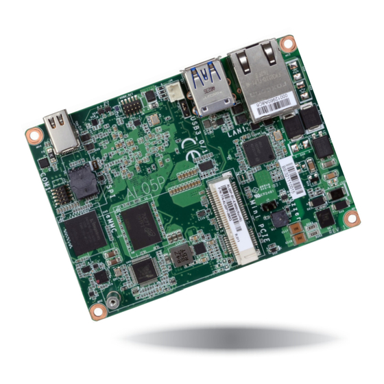
Chapter 2 - Hardware Installation Board Layout Intel I211AT or LAN/PoE PD optional I210IT Buzzer 12V DC Connector for Debug USB 0-1 (opt.) USB 3.1 Gen1 Mini PCIe Battery Standby Intel Power Atom USB 6-7 USB 2.0 F81803 SPI Flash BIOS Mini DP++ Front eMMC... -
Page 9: System Memory
Block Diagram Important: Electrostatic discharge (ESD) can damage your board, processor, disk drives, add-in boards, and other components. Perform installation procedures at an ESD workstation only. If such a station is not available, you can provide some ESD protection by wear- Mini DP++ ing an antistatic wrist strap and attaching it to a metal part of the system chassis. -
Page 10: Rear Panel I/O Ports
® press Gigabit Ethernet controller AL05P is powered by power over ethernet (PoE) for industrial and signage use under PoE envi- ronment. The LAN port enables the system board to connect to a local area network and 48V DC power by means of a network hub. Using a voltage more than the recommended range may fail to boot the system or cause damage to the system board. -
Page 11: Graphics Interface
Graphics Interface USB Ports The display port consists of the following: • 1 Mini DP++ port USB 1 USB 0 USB 3.1 Gen1 DATA- DATA- DATA+ USB 6-7 DATA+ USB 2.0 Mini DP++ The USB device allows data exchange between your computer and a wide range of simultane- Mini DP++ Port ously accessible external Plug and Play peripherals. -
Page 12: I/O Connectors
I/O Connectors Expansion Slot Digital I/O Connector Full-size Mni PCIe (PCIe/USB 2.0/SATA 3.0, optional USB 3.1 Gen1/USB 2.0) Digital I/O The Digital I/O connector supports 8-bit digital input/output signals to provide the ability of Mini PCI Express Slot monitoring and controlling the states of the connected external devices. The full-size Mini PCIe socket supports PCIe x1, USB 2.0, and SATA 3.0 (optional USB 3.1 Gen1/USB 2.0) signals and is used to install a Mini PCIe card. -
Page 13: Com (Serial) Port
COM (Serial) Port COM 1 RS232 RS422 Full Duplex RS485 DCD- DATA- DATA+ DTR- DSR- RTS- CTS- COM 1: RS232/422/485 COM 1 can be selected among RS232, RS422 and RS485. The serial port is asynchronous communication ports with 16C550A-compatible UARTs that can be used with modems, serial printers, remote display terminals, and other serial devices. -
Page 14: Smbus Connector
SMBus Connector Front Panel Connector Front Panel SMBus ATX-SW This switch is used to power on or off the system. RESET This switch allows you to reboot without having to power off the system. The System Management Bus (SMBus) connector is used to connect SMBus devices. It is a multiple device bus that allows multiple chips to connect to the same bus and enable each one to act as a master by initiating data transfer. -
Page 15: Battery
Battery 12V DC Connector for Debug (optional) 12V DC Connector for Debug (optional) 12VSB Battery Connector +3.3V 12V DC connector (optional) is for debug. Connect to the Battery battery connector The lithium ion battery powers the real-time clock and CMOS memory. It is an auxiliary source of power when the main power is shut off. -
Page 16: Chapter 3 - Bios Setup
Chapter 3 - BIOS Setup Legends Overview Keys Function The BIOS is a program that takes care of the basic level of communication between the CPU and peripherals. It contains codes for various advanced features found in this system board. Right and Left arrows Moves the highlight left or right to select a menu. -
Page 17: Main
Boot Exit Setting incorrect field values may cause the system to malfunction. This is the help for the Project Name AL05P hour, minute, second field. BIOS Version B192.19A Valid range is from 0 to 23, 0 to 59, 0 to 59. IN- Intel(R) Pentium(R) CPU N4200 @ 1.10GHz... - Page 18 ACPI Configuration Note: If "Quiet Boot" of Boot menu is set to enabled, "BGRT Logo" will appear for This section configures the system ACPI parameters. configuration. Refer to the Boot menu in this chapter for more information. InsydeH2O Setup Utility Rev.
- Page 19 CPU Configuration Video Configuration This section is used to configure the CPU. This section configures the video settings. InsydeH2O Setup Utility Rev. 5.0 InsydeH2O Setup Utility Rev. 5.0 Advanced Advanced Select which of IGD/PCIe Primary Display <IGD> Graphics device should be E n a b l e / D i s a b l e I n t e l EIST <Enabled>...
- Page 20 SATA Configuration PCI Express Configuration This section configures the SATA controller. This section configures settings relevant to PCI Express root ports. InsydeH2O Setup Utility Rev. 5.0 Advanced InsydeH2O Setup Utility Rev. 5.0 Control the PCI Express Advanced PCI Express Root Port 2 (Mini PCIE) ...
- Page 21 Console Redirection InsydeH2O Setup Utility Rev. 5.0 Advanced This section configures settings relevant to console redirection. PCI Express Root Port 4 (LAN) <Enabled> Control the PCI Express Root Port. Enable: Enable PCIe root port InsydeH2O Setup Utility Rev. 5.0 Disable: Disable PCIe root port Advanced Enable Console Redirec-...
- Page 22 When Console Serial Redirect is set to enabled, the screen will appear like below: COM1 InsydeH2O Setup Utility Rev. 5.0 InsydeH2O Setup Utility Rev. 5.0 Advanced Advanced Enable Console Redirec- Console Serial Redirect <Enabled> COM1 tion Function Terminal Type <VT_100> PortEnable <Enabled>...
- Page 23 When UseGlobalSetting is set to disabled, the screen will appear like below: SIO FINTEK81803 This section configures the system super I/O chip parameters. InsydeH2O Setup Utility Rev. 5.0 Advanced InsydeH2O Setup Utility Rev. 5.0 COM1 Advanced PortEnable <Enabled> Configure Serial port using UseGlobalSetting <Disabled>...
-
Page 24: Security
Security PC Health Status This section displays the PC health status. InsydeH2O Setup Utility Rev. 5.0 InsydeH2O Setup Utility Rev. 5.0 Main Advanced Security Boot Exit Advanced When Hidden, don’t ex- Current TPM Device <TPM 2.0 (FTPM)> poses TPM to 0 TPM State All Hierarchies Enabled, UnOwned Voltage... -
Page 25: Boot
Boot Note: AL05P only support UEFI boot, no Legacy boot. InsydeH2O Setup Utility Rev. 5.0 Main Advanced Security Boot Exit The number of seconds that the firmware will wait Setup Prompt Timeout before booting the original Numlock <On> default boot selection. -
Page 26: Exit
To update the BIOS, you will need the new BIOS file and a flash utility. Please contact techni- cal support or your sales representative for the files. For updating Insyde BIOS in UEFI mode, you may refer to the how-to-video at https://www.dfi.com/Knowledge/Video/31 . InsydeH2O Setup Utility Rev. -
Page 27: Notice: Bios Spi Rom
Notice: BIOS SPI ROM 1. The Intel Trusted Execution Engine has already been integrated into this system board. ® Due to the safety concerns, the BIOS (SPI ROM) chip cannot be removed from this system board and used on another system board of the same model. 2. -
Page 28: Chapter 4 - Supported Software
INF files so that ® the Intel chipset can be recognized and configured properly in the system. To install the utility, download “AL05P Chipset Driver” zip file at our website. 1. Setup is ready to install the utility. Click “Next”. - Page 29 Intel Graphics Driver 3. Go through the readme document for system re- quirements and installation To install the driver, download “AL05P Graphics Driver” zip file at our website. tips then click “Next”. 1. Setup is now ready to install the graphics driver.
- Page 30 Intel LAN Driver 4. Click “Install” to begin the installation. To install the driver, download “AL05P LAN Driver” zip file at our website. 1. Setup is ready to install the driver. Click “Next”. 5. The step displays the installing status in the prog- ress.
- Page 31 Intel Trusted Execution Engine Driver 3. The step displays the installing status in the To install the driver, download “AL05P TXE Driver” zip file at our website. progress. 1. Tick “I accept the terms in the License Agreement“ and then click “Next.”...
- Page 32 SIO Driver 3. Go through the readme docu- ment for system requirements and To install the driver, download “AL05P SIO Driver” zip file at our website. installation tips then click “Next”. 1. Setup is ready to install the driver. Click “Next”.
- Page 33 5. Setup is now installing the driver. 6. Click “Yes, I want to restart this computer now” then click “Finish”. Restarting the system will allow the new software installation to take effect.
Need help?
Do you have a question about the AL05P and is the answer not in the manual?
Questions and answers