Table of Contents
Advertisement
Quick Links
Advertisement
Table of Contents

Subscribe to Our Youtube Channel
Related Manuals for DFI AL051


Summary of Contents for DFI AL051
- Page 1 AL051 Embedded SBC 2.5” User’s Manual 469-M-2002...
-
Page 2: Copyright
Copyright FCC and DOC Statement on Class B This publication contains information that is protected by copyright. No part of it may be re- This equipment has been tested and found to comply with the limits for a Class B digital produced in any form or by any means or used to make any transformation/adaptation without device, pursuant to Part 15 of the FCC rules. -
Page 3: Table Of Contents
Table of Contents I/O Connectors ..............18 Digital I/O Connector ............. 18 Front Audio Connector ........... 18 Copyright ........... 2 COM (Serial) Port ............19 SATA (Serial ATA) Connector ........... 20 Trademarks ..........2 Expansion Slots ............. 20 SMBus Connector ............21 FCC and DOC Statement on Class B ... -
Page 4: Warranty
Warranty Static Electricity Precautions 1. Warranty does not cover damages or failures that arised from misuse of the product, in- It is quite easy to inadvertently damage your PC, system board, components or devices even ability to use the product, unauthorized replacement or alteration of components and prod- before installing them in your system unit. -
Page 5: About The Package
About the Package The package contains the following items. If any of these items are missing or damaged, please contact your dealer or sales representative for assistance. • One AL051 board • One Serial ATA data cable (Length: 155mm) •... -
Page 6: Chapter 1 - Introduction
1 x Audio (Line-out/Mic-in) SATA 1 x SATA 3.0 (up to 6Gb/s) 1 x 8-bit DIO SMBus 1 x SMBus WATCHDOG Output & System Reset, Programmable via Software from 1 to 255 Seconds TIMER Interval SECURITY fTPM2.0 Chapter 1 Introduction www.dfi.com... -
Page 7: Features
USB 2.0. It is a marked im- provement in device transfer speeds between your computer and a wide range of simultane- ously accessible external Plug and Play peripherals. Chapter 1 Introduction www.dfi.com... -
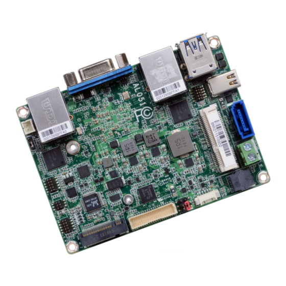
Page 8: Chapter 2 - Hardware Installation
Chapter 2 Chapter 2 - Hardware Installation Board Layout 2-Pin Terminal Block Mini DP++ USB 3.1 Gen 1 SATA 3.0 (DC 12V) USB 0-1 Standby Power LED SATA 0 Flash Buzzer USB 2.0 BIOS Mini PCIe USB 2-3 LCD/Inverter LAN 1 &... -
Page 9: Block Diagram
Chapter 2 Block Diagram Mechanical Drawing IT6516 DDR3L 1866MHz Channel A 69.08 SODIMM Mini DP++ PTN3460 LVDS PCIe x1 GLAN 1 I211AT I210 IT (opt.) SATA 3.0 SATA 1x PCIe x1 GLAN 2 I211AT I210 IT SATA 3.0 (opt.) Intel Atom ®... -
Page 10: System Memory
Chapter 2 Installing the SODIMM Module Important: Electrostatic discharge (ESD) can damage your board, processor, disk drives, add-in Note: boards, and other components. Perform installation procedures at an ESD workstation The system board used in the following illustrations may not resemble the actual only. -
Page 11: Jumper Settings
Chapter 2 5. Grasping the module by its edges, align the module into the socket at an approximately 30 Jumper Settings degrees angle. Apply firm even pressure to each end of the module until it slips down into the socket. The contact fingers on the edge of the module will almost completely disappear Panel Power Select inside the socket. -
Page 12: Signal Select
Chapter 2 M.2 Signal Select 1-2 On: SATA (default) 2-3 On: PCIe JP5 is used to select the M.2 signal: SATA (default) or PCIe. Chapter 2 Hardware Installation www.dfi .com... -
Page 13: Heat Spreader Assembly
H e a r f a c I n t e S i d e C P U s i s h a s T o C L e g Chapter 2 Hardware Installation www.dfi.com e r * r e a d... - Page 14 H e a f * 4 f * 4 Chapter 2 Hardware Installation r f a c r f a c www.dfi.com d - o f d - o f I n t e I n t e S t a n...
-
Page 15: Rear Panel I/O Ports
The rear panel I/O consists of the following ports: • 1 2-pin terminal block (DC 12V) • 1 Mini DP++ port • 2 USB 3.1 Gen 1 ports • 2 GbE (RJ-45) • 1 VGA port Chapter 2 Hardware Installation www.dfi.com... -
Page 16: Graphics Interfaces
Driver Installation Driver Installation Install the LAN drivers. Refer to Chapter 4 for more information. Install the graphics driver. Refer to Chapter 4 for more information. Chapter 2 Hardware Installation www.dfi.com... -
Page 17: Usb Ports
USB port cables to a connector. BIOS Settings Configure the onboard USB in the “USB Boot” field of the Boot menu in the BIOS. Refer to Chapter 3 for more information. Chapter 2 Hardware Installation www.dfi.com... -
Page 18: I/O Connectors
The front audio connector allows you to connect to line-out and mic-in jacks that are at the front panel of your system. Function Function DIO7 DIO6 Driver Installation DIO5 DIO4 Install the audio driver. Refer to Chapter 4 for more information. DIO3 DIO2 DIO1 DIO0 Chapter 2 Hardware Installation www.dfi.com... -
Page 19: Com (Serial) Port
BIOS Setting Configure the serial port in the “SIO FINTEK81803” submenu of the Advanced menu in the BIOS. Refer to Chapter 3 for more information. Chapter 2 Hardware Installation www.dfi.com... -
Page 20: Sata (Serial Ata) Connector
ATA data cable to a SATA connector and the other end to your Serial ATA device. age. BIOS Setting Configure the Serial ATA drive in the Advanced menu (“SATA Configuration” submenu) of the BIOS. Refer to Chapter 3 for more information. Chapter 2 Hardware Installation www.dfi.com... -
Page 21: Smbus Connector
On Suspend) state, it will blink every second. When the system is in the S3 (STR - Suspend To RAM) state, it will blink every 4 seconds. Pin Pin Name Pin Pin Name HDD_LED Reset Button RESET- HDD-LED SUS_LED Power Button PWR-BTN PWR-LED V_LED Chapter 2 Hardware Installation www.dfi.com... -
Page 22: Lvds Lcd Panel Connector
3 for more information. Panel Power Panel Power Note: 1. DFI board's LVDS LCD panel connector: 2. DFI board's LCD/Inverter & SATA power connector: Manufacturer: V-STAR Manufacturer: E-call Part No: W100V40TP2 Part No: 0110-3221050 Description: 2*20, 1.0mm, BOX header Description: 1*5pin, 1.25mm, Wafer... -
Page 23: Battery
Safety Measures • Danger of explosion if battery incorrectly replaced. • Replace only with the same or equivalent type recommended by the manufacturer. • Dispose of used batteries according to local ordinance. Chapter 2 Hardware Installation www.dfi.com... -
Page 24: Chapter 3 - Bios Setup
<Enter>. disappears before you respond, restart the system or press the “Reset” button. You may also restart the system by pressing the <Ctrl> <Alt> and <Del> keys simultaneously. Chapter 3 BIOS Setup Chapter 3 BIOS Setup www.dfi.com www.dfi.com... -
Page 25: Insyde Bios Setup Utility
Boot Exit Setting incorrect field values may cause the system to malfunction. This is the help for the Project Name AL051 hour, minute, second field. BIOS Version B185.31A Valid range is from 0 to 23, 0 to 59, 0 to 59. IN- Intel(R) Pentium(R) CPU N4200 @ 1.10GHz... - Page 26 This field is to specify what state the system should be in when power is re-applied after a power failure (G3, the mechanical-off, state). Always On The system working state. Always Off Off, except for trickle current to devices such as the power button. Chapter 3 BIOS Setup Chapter 3 BIOS Setup www.dfi.com www.dfi.com...
- Page 27 Enable or disable CPU Power Management. It allows CPU to go to C States when it’s not 100% utilized. LCD Panel Color Depth Select the LCD panel color depth: 18 Bit, 24 Bit, 36 Bit or 48 Bit. Chapter 3 BIOS Setup Chapter 3 BIOS Setup www.dfi.com www.dfi.com...
- Page 28 Select Serial ATA controller(s) speed from Gen1 (1.5 Gbit/s), Gen2 (3.0 Gbit/s) or Gen 3 (6.0 Gbit/s). Serial ATA Port 0/1 and Hot Plug These fields are used to enable or disable the serial ATA ports and their hot plug func- tion. Chapter 3 BIOS Setup Chapter 3 BIOS Setup www.dfi.com www.dfi.com...
- Page 29 Select the speed of the PCI Express Root Port: Auto, Gen1 or Gen2. port Disable: Disable PCIe root port Help ↑/↓ Select Item F5/F6 Change Values Setup Defaults Exit ←/→ Select Item Enter Select SubMenu Save and Exit Chapter 3 BIOS Setup Chapter 3 BIOS Setup www.dfi.com www.dfi.com...
- Page 30 Select data bits: 7 Bits or 8 Bits. Parity Select parity bits: None, Even or Odd. Stop Bits Select stop bits: 1 Bit or 2 Bits. Flow Control Select flow control type: None, RTS/CTS or XON/XOFF. Chapter 3 BIOS Setup Chapter 3 BIOS Setup www.dfi.com www.dfi.com...
- Page 31 COM port will be the same as those in Console Redirection section. When disabled the global setting, setting of the COM port can be configured indepen- dently in this section. Chapter 3 BIOS Setup Chapter 3 BIOS Setup www.dfi.com www.dfi.com...
- Page 32 Choose RS232/RS422/RS485 (Peer-to-Peer) for COM type. Enable or disable the watchdog function. A counter will appear if you select to enable WDT. Input any value between 1 to 255 seconds. Chapter 3 BIOS Setup Chapter 3 BIOS Setup www.dfi.com www.dfi.com...
-
Page 33: Security
Disabled Suppoort Network Stack Set the supervisor’s password and the length of the password must be greater than UEFI IPv4/IPv6 one character. USB Boot Enable or disable booting to USB boot devices. Chapter 3 BIOS Setup Chapter 3 BIOS Setup www.dfi.com www.dfi.com... -
Page 34: Exit
Chapter 3 Exit Note: AL051 only support UEFI boot, no Legacy boot. InsydeH2O Setup Utility Rev. 5.0 Main Advanced Security Boot Exit Exit system setup and save your changes. Exit Saving Changes Load Optimal Defaults Discard Changes Save Setting to file Help ↑/↓... -
Page 35: Updating The Bios
For updating Insyde BIOS in UEFI mode, Due to the safety concerns, the BIOS (SPI ROM) chip cannot be removed from this system you may refer to the how-to-video at https://www.dfi.com/Knowledge/Video/31 . board and used on another system board of the same model. -
Page 36: Chapter 4 - Supported Software
INF files so that ® the Intel chipset can be recognized and configured properly in the system. To install the utility, download “AL051 Chipset Driver” zip file at our website. 1. Setup is ready to install the utility. Click “Next”. - Page 37 Intel Graphics Driver 3. Go through the readme document for system re- quirements and installation To install the driver, download “AL051 Graphics Driver” zip file at our website. tips then click “Next”. 1. Setup is now ready to install the graphics driver.
- Page 38 Chapter 4 Audio Driver Intel LAN Driver To install the driver, download “AL051 Audio Driver” zip file at our website. To install the driver, download “AL051 LAN Driver” zip file at our website. 1. Setup is ready to install the 1.
- Page 39 Chapter 4 Intel Trusted Execution Engine Driver 4. Click “Install” to begin the installation. To install the driver, download “AL051 TXE Driver” zip file at our website. 1. Tick “I accept the terms in the License Agreement“ and then click “Next.”...
- Page 40 SIO Driver 3. The step displays the installing status in the progress. To install the driver, download “AL051 SIO Driver” zip file at our website. 1. Setup is ready to install the driver. Click “Next”. 4. Click “Finish“ when the installation is complete.
- Page 41 4. Setup is ready to install the driver. 6. Click “Yes, I want to restart Click “Next”. this computer now” then click “Finish”. Restarting the system will allow the new software installation to take effect. Chapter 4 Supported Software www.dfi.com...
-
Page 42: Appendix A - Troubleshooting Checklist
AC outlet. If necessary, try another outlet. 3. Check that the video input cable is properly attached to the monitor and the system’s display adapter. 4. Adjust the brightness of the display by turning the monitor’s brightness control knob. Appendix A Troubleshooting Checklist www.dfi.com... - Page 43 Nothing happens when a key on the keyboard was pressed. 1. Make sure the keyboard is properly connected. 2. Make sure there are no objects resting on the keyboard and that no keys are pressed dur- ing the booting process. Appendix A Troubleshooting Checklist www.dfi.com...
Need help?
Do you have a question about the AL051 and is the answer not in the manual?
Questions and answers