Table of Contents
Advertisement
Quick Links
Advertisement
Table of Contents

Related Manuals for Digi ConnectCore 8M Mini


Summary of Contents for Digi ConnectCore 8M Mini
- Page 1 ConnectCore 8M Mini Development Board Hardware Reference Manual...
- Page 2 Information in this document is subject to change without notice and does not represent a commitment on the part of Digi International. Digi provides this document “as is,” without warranty of any kind, expressed or implied, including, but not limited to, the implied warranties of fitness or merchantability for a particular purpose.
- Page 3 To provide feedback on this document, email your comments to techcomm@digi.com Include the document title and part number (ConnectCore 8M Mini Development Board Reference Manual, 90002455 A) in the subject line of your email. ConnectCore 8M Mini Development Board Reference Manual...
-
Page 4: Table Of Contents
Contents About the ConnectCore 8M Mini development board Features and functionality Placement and connectors Interfaces Power DC-in connectors Power architecture configuration Coin cell/Supercap Battery connector Power and reset buttons System boot Debug JTAG Console ports USB recovery Communication Gigabit Ethernet... -
Page 5: About The Connectcore 8M Mini Development Board
About the ConnectCore 8M Mini development board The Digi ConnectCore 8M Mini Development Board is a system-on-module (SOM) development kit that streamlines the prototyping of a wide range of industrial and medical applications. Built on the i.MX 8M Mini processor with power-efficient quad ARM® Cortex®-A53 and Cortex-M4 cores, Digi ConnectCore 8M Mini combines pre-certified wireless connectivity (802.11 a/b/g/n/ac and... - Page 6 About the ConnectCore 8M Mini development board Features and functionality x5 GPIOs CAN FD (through SPI interface) RS-485 PCI Express Mini Card slot supporting half- and full-size cards, with USB, PCIe and Micro- SIM connection. Audio interfaces: x1 3.5 mm headphone jack x1 3.5 mm microphone jack...
-
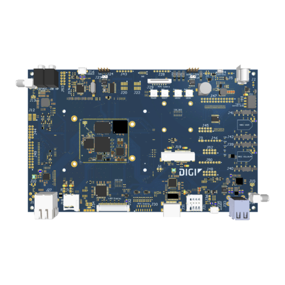
Page 7: Placement And Connectors
About the ConnectCore 8M Mini development board Placement and connectors Placement and connectors ConnectCore 8M Mini Development Board Reference Manual... - Page 8 About the ConnectCore 8M Mini development board Placement and connectors Connector Interface Manufacturer Manufacturer Part Number 5 V power-in jack Bobbintron SCD443CCS011B00G Alternative 5 V power-in TE Connectivity 640456-2 MCA power consumption Coin-cell Molex 53047-0210 Battery connector TE Connectivity 640456-2...
- Page 9 About the ConnectCore 8M Mini development board Placement and connectors Connector Interface Manufacturer Manufacturer Part Number u.FL antenna connector Hirose U.FL-R-SMT(10) SMA antenna connector Bobbintron SMA A700T u.FL antenna connector Hirose U.FL-R-SMT(10) Console (USB) Kycon KMMX-ABSMT5SG-30TR Console (TTL) MicroSD Amphenol...
- Page 10 About the ConnectCore 8M Mini development board Placement and connectors Connector Interface Manufacturer Manufacturer Part Number Wireless signals UARTs GPIOs SAI1 Wireless signals Clocks SMA antenna connector Bobbintron SMA A700T Power rails Audio Supercap ConnectCore 8M Mini Development Board Reference Manual...
- Page 11 Interfaces The following interfaces are available on the ConnectCore 8M Mini: Power System boot Debug Communication Multimedia Storage interfaces User interfaces ConnectCore 8M Mini Development Board Reference Manual...
-
Page 12: Interfaces Power
Power DC-in connectors The input voltage of the ConnectCore 8M Mini Development Board is 5 V. You can use one of two connectors to power the entire system. Note that you can only enable one at a time. DC-in power jack connector J2, a 2-pin, 2.54 mm pitch connector:... -
Page 13: Battery Connector
VSYS2 Battery power supply Ground Power applied to this power supply feeds the part of the ConnectCore 8M Mini SOM that supports battery applications. Power and reset buttons One power button (SW1) and one reset button (SW2) are included on the development board. These... -
Page 14: Debug
J22, a 10 pin (2x5), 1.27 mm pitch connector: Signal name Description VCC_MCA 3.3 V supply voltage of the MCA SWD_DIO Data I/O line Ground SWD_CLK Clock line Ground Not connected Not connected Not connected Ground SYS_RESET Reset line ConnectCore 8M Mini Development Board Reference Manual... -
Page 15: Console Ports
The development board includes a dedicated USB micro AB-type port (J35) for recovery. This port detects when a cable is plugged in and automatically switches the USB1 bus of the CPU from its ConnectCore 8M Mini Development Board Reference Manual... -
Page 16: Communication
LEDs, as specified in the following table: Green LED Yellow LED Link/activity status 10M/100M Link BLINK 10M/100M Active 1000M Link BLINK 1000M Active RS-485 The development board supports one RS-485 half-duplex bus, available on an expansion connector (J26): ConnectCore 8M Mini Development Board Reference Manual... -
Page 17: Can
Mini PCIe The development board provides one Mini PCI Express socket (J19) supporting USB, PCIe and I2C connection to the ConnectCore 8M Mini module. A micro SIM socket is also connected to the Mini PCI Express slot. ConnectCore 8M Mini Development Board Reference Manual... -
Page 18: Xbee
The ConnectCore 8M Mini System-on-Module supports only one MIPI-DSI display interface. On the ConnectCore 8M Mini Development Board, this MIPI-DSI display is managed so that three different display interfaces are supported, although only one of them can work at a time. -
Page 19: Mipi-Csi Camera
The development board provides a MIPI camera serial interface (MIPI-CSI) over a 15-pin connector (J29): Signal name Description 3V3_SOM_EXT 3.3 V power supply MIPI_CSI_I2C_SDA i.MX8M I2C2 bus data line MIPI_CSI_I2C_SCL i.MX8M I2C2 bus clock line Not connected ConnectCore 8M Mini Development Board Reference Manual... -
Page 20: Audio
3.5 mm headphone jack 3.5 mm microphone jack x2 speaker outputs (left and right) x1 line-out output x2 line-in inputs The speakers, line-out signals, and line-in signals are available over a 10-pin connector (J53): ConnectCore 8M Mini Development Board Reference Manual... -
Page 21: Storage Interfaces
Three LEDs are available on the development board: one green, one yellow, and one red. All of them are connected to SOM GPIOs. User button Two buttons are available on the development board, both of them connected to the SOM. ConnectCore 8M Mini Development Board Reference Manual...
Need help?
Do you have a question about the ConnectCore 8M Mini and is the answer not in the manual?
Questions and answers