Table of Contents
Advertisement
Advertisement
Table of Contents

Subscribe to Our Youtube Channel
Related Manuals for Digi XBee Grove Development Board Series


Summary of Contents for Digi XBee Grove Development Board Series
- Page 1 XBee Grove Development Board User Guide...
- Page 2 Information in this document is subject to change without notice and does not represent a commitment on the part of Digi International. Digi provides this document “as is,” without warranty of any kind, expressed or implied, including, but not limited to, the implied warranties of fitness or merchantability for a particular purpose.
- Page 3 Feedback To provide feedback on this document, email your comments to techcomm@digi.com Include the document title and part number (XBee Grove Development Board User Guide, 90001457- 13 V) in the subject line of your email. XBee Grove Development Board User Guide...
-
Page 4: Table Of Contents
Contents Overview Development board variants XBee THT Grove Development Board XBee SMT Grove Development Board XBee surface-mount (SMT) Grove development board XBee through-hole (TH) Grove development board Mechanical XBee THT Grove Development Board variant XBee SMT Grove Development Board variant Power supply XBee THT Grove Development Board power supply XBee SMT Grove Development Board power supply Power supply battery connector... - Page 5 On/sleep LED connection to DIO9 Potentiometer XBee THT Grove Development Board Potentiometer XBee SMT Grove Development Board Potentiometer XBee THT Grove Development Board I2C bus XBee SMT Grove Development Board I2C bus XBee/XBee-PRO connection to Grove sensor Grove I2C connector pinout Grove Connectors THT board Grove connectors pinout SMT board Grove connectors pinout...
- Page 6 Overview This section provides an overview of the XBee Grove Development Board. XBee Grove Development Board User Guide...
-
Page 7: Overview
Overview Development board variants Development board variants The THT and SMT are the two variants of the board. XBee THT Grove Development Board XBee SMT Grove Development Board XBee Grove Development Board User Guide... -
Page 8: Xbee Surface-Mount (Smt) Grove Development Board
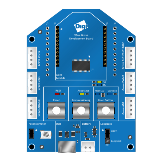
Overview XBee surface-mount (SMT) Grove development board XBee surface-mount (SMT) Grove development board This picture shows the XBee SMT Grove development board and the table that follows explains the callouts in the picture. XBee Grove Development Board User Guide... - Page 9 Overview XBee surface-mount (SMT) Grove development board Number Item Description SMT XBee socket Grove The board provides eight vertical Grove connectors connected to XBee connectors DIO lines. Reset button Button connected to the XBee reset pin. User button Button connected to the XBee DIO4 line. The button shares the same DIO line with one user LED.
-
Page 10: Xbee Through-Hole (Th) Grove Development Board
Overview XBee through-hole (TH) Grove development board XBee through-hole (TH) Grove development board This picture shows the XBee TH Grove development board and the table that follows explains the callouts in the picture. XBee Grove Development Board User Guide... - Page 11 Overview XBee through-hole (TH) Grove development board Number Item Description Through-hole Two 10-pin, 2 mm pitch. XBee sockets Grove The board provides six vertical Grove connectors, connected to XBee connectors DIO lines. Association LED connected to the XBee association pin. indicator RSSI indicator LED connected to the XBee RSSI pin.
-
Page 12: Mechanical
Overview Mechanical Mechanical There are two variants of the XBee Grove Development Board: THT variant is 48.8 mm x 66 mm SMT variant is 53.68 mm x 72.60 mm with a shape similar to a regular XBee module. The board provides four 3.2 mm assembly drills. XBee THT Grove Development Board variant XBee SMT Grove Development Board variant XBee Grove Development Board User Guide... -
Page 13: Power Supply
Overview Power supply Power supply You can power the XBee Grove Development Board from the 5 V supply available on the USB connector or from an external battery connected to a 2-pin, 2 mm pitch, PH-type connector from JST. When you power the board from both supplies, it uses the USB. The board has a 3.3 V regulator that generates 500 mA supply. -
Page 14: Power Supply Battery Connector
Overview XBee connector Power supply battery connector The following table shows the pinout of the battery connector: Battery connector Signal Comments VBAT Battery supply input Note The power supply battery connector is not mounted in the board. XBee connector The XBee THT Grove Development Board provides two 10-pin, THT, 2 mm pitch sockets to connect a THT XBee module. -
Page 15: Xbee Tht Grove Development Board Xbee Connector
XBee THT Grove Development Board XBee connector The board provides footprints for two 10-pin, THT, 2.54 mm pitch connectors. You can use these footprints to solder a pin header on the top or bottom to access the XBee signals or to connect the XBee Grove Development Board to a bread board. Left Right Signal... - Page 16 Left Right XBEE_RX To serial to USB device DIO9 To On/Sleep LED DIO12 To GROVE_DIO12 VREF RESET_N To reset button ASSOC_LED To association LED RSSI/PWM0 To RSSI LED and GROVE_PWM XBEE_RTS_N To serial to USB device DIO11/I2C_SDA To GROVE_I2C To potentiometer XBEE_PIN8 Connected to breadboard header To GROVE_AD2...
-
Page 17: Xbee Smt Grove Development Board Xbee Connector
XBee SMT Grove Development Board XBee connector The XBee SMT Grove Development Board provides three spring sockets. A spring header is a custom Digi header that provides a reliable connection to SMT XBee modules without soldering the module in place. - Page 18 Left Bottom Right XBEE_TX To serial to USB device DIO1/I2C_SCL To GROVE_I2C XBEE_RX To serial to USB device To potentiometer DIO12 To GROVE_DIO12 To GROVE_AD3 RESET_N To reset button XBEE_RTS_N To serial to USB device RSSI/PWM0 To RSSI LED and GROVE_ ASSOC_LED To association LED PWM0...
-
Page 19: Usb
Overview The XBee Grove Development Board includes a micro USB connector and an FT232RL USB to RS-232 converter to communicate with the serial port of the XBee. A green LED and a yellow LED show the status of the TX and RX lines. The hardware flow control signals of the XBee (XBee_RTS and XBee_CTS) connect to the FT232RL device. -
Page 20: Xbee Smt Grove Development Board Usb
Overview XBee SMT Grove Development Board USB USB VBUS line The following graphic illustrates how the USB powers the board through the VBUS line. XBee Grove Development Board User Guide... -
Page 21: Reset Button
Overview Reset button Reset button The XBee Grove Development Board has a reset button to reboot the XBee module. XBee THT Grove Development Board Reset button XBee SMT Grove Development Board Reset button XBee Grove Development Board User Guide... -
Page 22: Commissioning Button
Overview Commissioning button Commissioning button The XBee Grove Development Board has a push button connected to the commissioning pin of the XBee module. The commissioning pin of the XBee is also connected to the Grove AD0 connector. You can use the commissioning push button in Zigbee or DigiMesh to help deploy devices in a network. XBee THT Grove Development Board Commissioning button XBee SMT Grove Development Board Commissioning button XBee Grove Development Board User Guide... -
Page 23: Commissioning Pin And Grove Ad0 Connection
Overview Commissioning button Commissioning pin and Grove AD0 connection XBee Grove Development Board User Guide... -
Page 24: Association Led
Overview Association led Association led The XBee Grove Development Board provides an LED connected to the association pin of the XBee module. XBee THT Grove Development Board Association LED XBee SMT Grove Development Board Association LED XBee Grove Development Board User Guide... -
Page 25: Rssi Led
Overview RSSI led RSSI led The XBee Grove Development Board provides an LED connected to the RSSI/PWM0 pin of the XBee module. The RSSI/PWM signal is also connected to the PWM Grove connector. If the PWM0 pin (P0) is configured as RSSI, the brightness of this LED displays the signal strength of the last packet received. -
Page 26: Pwm0 Rssi Configuration
Overview RSSI led PWM0 RSSI configuration XBee Grove Development Board User Guide... -
Page 27: User Led And User Button
Overview User LED and User button User LED and User button The XBee Grove Development Board provides a user LED and a user button. Both share the same XBee I/O pin, DIO4. Although the user LED and user button share the same pin, you can use only one at a time. XBee THT Grove Development Board User LED and User button XBee SMT Grove Development Board User LED and User button User LED and User Button connection to DIO4... - Page 28 Overview User LED and User button XBee Grove Development Board User Guide...
-
Page 29: On/Sleep Led
Overview On/sleep LED On/sleep LED The XBee Grove Development Board provides an LED connected to the On/Sleep pin (DIO9). This LED is on when the XBee module is awake, and off when it is asleep. XBee THT Grove Development Board On/Sleep LED XBee SMT Grove Development Board On/Sleep LED XBee Grove Development Board User Guide... -
Page 30: On/Sleep Led Connection To Dio9
Overview On/sleep LED On/sleep LED connection to DIO9 The following graphic illustrates the connection between the on/sleep LED and the On/sleep pin, DIO9. XBee Grove Development Board User Guide... -
Page 31: Potentiometer
Overview Potentiometer Potentiometer The XBee Grove Development Board provides a 10K potentiometer to generate analog signal between 3.3V and 0V. You can use the jumper to disconnect the 3.3V supply from the potentiometer to save power when not in use. XBee THT Grove Development Board Potentiometer The output of the potentiometer is connected to the AD3 pin (D3) of the XBee in the THT board. -
Page 32: Xbee Smt Grove Development Board Potentiometer
Overview Potentiometer XBee SMT Grove Development Board Potentiometer The output of the potentiometer is connected to AD2 pin (D2) of the XBee in the SMT board. XBee Grove Development Board User Guide... -
Page 33: I2C
Overview The XBee Grove Development Board provides an I2C bus that you can use with XBee programmable modules. XBee THT Grove Development Board I2C bus XBee SMT Grove Development Board I2C bus XBee/XBee-PRO connection to Grove sensor Regular XBee/XBee-PRO modules do not provide an I2C bus, but you can connect a digital Grove sensor. -
Page 34: Grove I2C Connector Pinout
Overview Grove I2C connector pinout The following table shows the pinout of the Grove I2C connector: Grove I2C Signal DIO1/I2C_SCL DIO11/I2C_SDA 3.3V XBee Grove Development Board User Guide... -
Page 35: Grove Connectors
Overview Grove Connectors Grove Connectors The XBee Grove Development Board provides several Grove connectors connected to the XBee pins: THT boards include six Grove connectors: Two connectors to digital I/O pins Two connectors to two digital/analog I/O pins One connector to the RSSI/PWM0 pin One connector to the I2C bus of the microcontroller placed in the socket (programmable XBee) SMT boards include eight Grove connectors:... -
Page 36: Tht Board Grove Connectors Pinout
Overview Grove Connectors THT board Grove connectors pinout The following tables show the pinout for the THT board Grove connectors: Grove DIO12 Signal Comments DIO12 3.3V Grove DIO4 Signal Comments DIO4 Signal connected to the user LED/button 3.3V Grove AD0 Signal Comments AD0/CB... - Page 37 Overview Grove Connectors Grove AD2 Signal Comments 3.3V XBee Grove Development Board User Guide...
-
Page 38: Smt Board Grove Connectors Pinout
Overview Grove Connectors SMT board Grove connectors pinout The following tables show the pinout for the SMT board Grove connectors: Grove DIO12 Signal Comments DIO12 3.3V Grove DIO4 Signal Comments DIO4 Signal connected to the LED/button 3.3V Grove AD0 Signal Comments AD0/CB Signal connected to the commissioning button... - Page 39 Overview Grove Connectors Grove PWM0 Signal Comments RSSI/PWM0 Signal connected to the RSSI LED 3.3V Grove DIO19 Signal Comments DIO19 3.3V Grove DIO18 Signal Comments DIO18 3.3V XBee Grove Development Board User Guide...
-
Page 40: Loopback Jumper
Overview Loopback jumper Loopback jumper The XBee Grove Development Board provides a three-pin jumper to connect the UART to the USB (normal mode) or to make a loopback connection between the RX and TX signals of the UART. In loopback mode, connect the RX line to the TX line, which transmits back any data received. You can use loopback in transparent mode to check the signal strength and perform a range test. -
Page 41: Schematic And Gerber Files
Schematic and Gerber files This section shows the schematics for the THT Grove Development Board and the SMT Grove Development board and provides links to download the Gerber files. XBee THT Grove Development Board XBee SMT Grove Development Board XBee Grove Development Board User Guide... -
Page 42: Xbee Tht Grove Development Board Schematic
XBee THT Grove Development Board schematic You can dowload a copy of the schematic for the XBee THT Grove Development Board. Gerber files You can download the Gerber files for the XBee THT Grove Development Board. -
Page 43: Xbee Smt Grove Development Board Schematic
XBee SMT Grove Development Board schematic You can download a copy of the schematic for the XBee SMT Development Board. Gerber files You can download the Gerber files for the XBee SMT Grove Development Board.
Need help?
Do you have a question about the XBee Grove Development Board Series and is the answer not in the manual?
Questions and answers