Advertisement
Quick Links
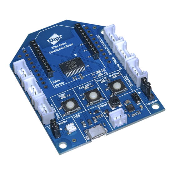
XBee Grove Development Board
The XBee Grove Development Board is a simple-to-use base unit. You can use it to evaluate
XBee modules, as it connects any XBee/XBee-PRO module to a PC or microcontroller. One of
the main features of the board is that it has several Grove connectors where you can plug in a
Grove Module. You can learn more about the
Grove module
on the Seeed Studio wiki.
There are two variants of the board: THT and SMT.
This guide includes the following topics:
•
Overview
XBee THT Grove Development Board
Advertisement

Related Manuals for Digi XBee Grove


Summary of Contents for Digi XBee Grove
- Page 1 XBee Grove Development Board The XBee Grove Development Board is a simple-to-use base unit. You can use it to evaluate XBee modules, as it connects any XBee/XBee-PRO module to a PC or microcontroller. One of the main features of the board is that it has several Grove connectors where you can plug in a Grove Module.
- Page 2 XBee SMT Grove Development Board...
- Page 4 Overview On this page: • Mechanical • Power supply • XBee connector • • Reset button...
- Page 5 User LED and User button • On/Sleep LED • Potentiometer • • Grove connectors • Loopback jumper Mechanical The XBee Grove Development Board is 44.8mm x 66mm with a shape similar to a regular XBee module. The board provides four 3.2 mm assemble drills.
-
Page 6: Power Supply
Power supply... - Page 7 The XBee Grove Development Board can be powered from the 5V supply available on the USB connector or from an external battery connected to a 2-pin, 2mm pitch, PH type connector from JST. When both supplies are available, the board is powered from the USB.
- Page 8 XBee signals or to connect the XBee Grove Development Board to a bread board. The following table shows the pinout of the XBee connector:...
- Page 9 10 AD0/CB and GROVE_AD0 The XBee Grove Development Board includes a microUSB connector and an FT232RL USB to RS232 converter to communicate with the serial port of the XBee. A green LED and a yellow LED show the status of the TX and RX lines.
-
Page 10: Reset Button
The USB connector is also used to power the board through the VBUS line. Reset button... - Page 11 The XBee Grove Development Board has a reset button to reboot the XBee module. Commissioning button The XBee Grove Development Board has a push button connected to the commissioning pin of the XBee module. The commissioning pin of the XBee is also connected to the Grove AD0 connector.
- Page 12 Association LED...
- Page 13 The XBee Grove Development Board provides an LED connected to the association pin of the XBee module. For more information about association, read the XBee Product Manual. RSSI LED The XBee Grove Development Board provides an LED connected to the RSSI/PWM0 pin of the XBee module.
- Page 14 User LED and User button The XBee Grove Development Board provides a user LED and a user button. Both share the same XBee I/O pin, DIO4. Although the user LED and user button share the same pin, you can use only one at a time.
- Page 15 On/Sleep LED The XBee Grove Development Board provides an LED connected to the On/Sleep pin (DIO9). This LED in on when the XBee module is awake, and off when it is asleep.
- Page 16 Potentiometer The XBee Grove Development Board provides a 10K potentiometer to generate analog signal between 3.3V and 0V. The output of the potentiometer is connected to the AD3 pin (D3) of the XBee.
- Page 17 One jumper is used to disconnect the 3.3V supply from the potentiometer to save power when it's not used.
- Page 18 The XBee Grove Development Board provides an I2C bus. This I2C bus can be used with XBee programmable modules. Regular XBee/XBee-PRO modules don't provide an I2C bus, but you can connect a digital Grove sensor.
- Page 19 3.3V Grove connectors The XBee Grove Development Board provides six Grove connectors connected to the XBee pins. Two connectors are connected to digital I/O pins, two connectors are connected to two digital/analog I/O pins, one connector is connected to the RSSI/PWM0 pin, and another is connected to the I2C bus of the microcontroller placed in the socket (programmable XBee.)
- Page 20 The following tables show the pinout of the Grove connectors: Grove DIO12 Signal Comments DIO12 3.3V Grove DIO4 Signal Comments DIO4 Signal connected to user LED/button 3.3V Grove AD0 Signal Comments AD0/CB Signal connected to commissioning button 3.3V Grove I2C Signal Comments DIO1/I2C_SCL...
- Page 21 The XBee Grove Development Board provides a three-pin jumper to connect the UART to the USB (normal mode) or to make a loopback connection between the RX and TX signals of the UART. In loopback mode, the RX line is connected to the TX line, which causes any received data to be transmitted back.
Need help?
Do you have a question about the XBee Grove and is the answer not in the manual?
Questions and answers