
Related Manuals for Bicker UPSI-1208DP Series


Summary of Contents for Bicker UPSI-1208DP Series
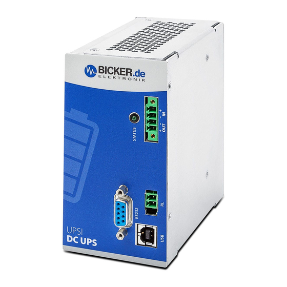
- Page 1 English User Manual UPSI-1208DPx UPS SYSTEM DIN-RAIL Bicker Elektronik GmbH Ludwig-Auer-Straße 23 | 86609 Donauwörth · Germany...
- Page 2 UPSI-1208DPx Legend of used symbols Symbol Description Attention! Important hazard warning. Do not dispose of in the domestic waste. Warning of electrical voltage. Revision Directory Date Change 31.03.2020 Initial version Revision 0-1 10.06.2020 Release version Revision 1 03.07.2020 Chapter B2 extended, Revision 1-1 Chapter B3 Environmental condition extended, Chapter C1 Input data Internal input fuse changed...
- Page 3 UPSI-1208DPx Revision 1-5...
-
Page 4: A Brief Specification Upsi-1208Dp2 / Upsi-1208Dp3
UPSI-1208DPx A Brief specification UPSI-1208DP2 / -DP3 12 V DC / 8 A 12 V DC UPS (DIN rail version) Integrated Supercaps (DP2) OR LiFePO4 battery (DP3) Up to 500 000 cycles (DP2) | up to 6 000 cycles (DP3) Capacity DP2: 5.73 kJ | DP3: 25 Wh ... - Page 5 UPSI-1208DPx Backup time* UPSI-1208DP2 Backup time* UPSI-1208DP3 *Backup time depends on battery capacitance, load and temperature. At very high or low temperatures a reduction of backup time occurs. Unless otherwise specified, the values apply to measurements at +25 °C Revision 1-5...
-
Page 6: Table Of Contents
UPSI-1208DPx Brief specification UPSI-1208DP2 / UPSI-1208DP3 ..........4 Introduction and description ................7 B1 Description of the product and its functions ....................7 B2 Intended use .................................8 Safety instructions ....................9 Technical Data ..................... 10 D1 General Technical Data ............................10 D2 Drawing ................................... -
Page 7: B Introduction And Description
The manual as well as all documents has to be read and followed strictly before installation. Otherwise in cer- tain situations warranty and guarantee can be cancelled partly or completely. Any liability on the part of Bicker Elektronik is excluded for possible existing errors as well as non-compliance with the instructions for use and installation. -
Page 8: B2 Intended Use
UPSI-1208DPx B2 Intended use This device is designed to be installed into a suitable enclosure which protects against electrical, water and fire hazards and can then be used indoors and outdoors. It is primary built for being mounted on a DIN Rail and is intended for professional use in applications such as industrial control, communication and measurement technology. -
Page 9: C Safety Instructions
UPSI-1208DPx C Safety instructions WARNING! Disregarding of following issues can result in electric shock, fire, serious injury or death. 1. Care must be taken to ensure proper and professional wiring. 2. The device pack must not be exposed to fire and temperatures outside the specification. 3. -
Page 10: D Technical Data
UPSI-1208DPx D Technical Data D1 General Technical Data INPUT DATA – UPSI-1208DP2 / UPSI-1208DP3 Unless otherwise stated, all specifications apply to 25 °C ambient temperature, 12 V DC input voltage and nominal output current (I Input voltage 12 V DC Input voltage range 11.5 V DC…16 V DC Electric strength max. - Page 11 UPSI-1208DPx OUTPUT DATA – UPSI-1208DP2 / UPSI-1208DP3 (NORMAL MODE) Unless otherwise stated, all specifications apply to 25 °C ambient temperature, 12 V DC input voltage and nominal output current (I Output voltage 12 VDC Output voltage range – 0.6 V DC max. (depending on load) Capacitive load 3000 µF (at start) Output current...
- Page 12 UPSI-1208DPx CONNECTION DATA INPUT / OUTPUT Connection method Screwable plug connector Conductor cross-section solid 0.129 mm² … 1.31 mm² (26 … 16 AWG) Conductor cross-section flexible 0.129 mm² … 1.31 mm² (26 … 16 AWG) Conductor cross-section with ferrule 0.129 mm² … 1.31 mm² (26 … 16 AWG) Stripping length 6 mm …...
- Page 13 UPSI-1208DPx CONNECTION DATA – RELAY Connection labeling Switch contact (potential free) Relay Status (configurable) Power Fail Alarm Switching voltage 24 V DC / 125 V AC Current carrying capacity 1 A (DC) / 0.5 A (AC) State - signal assignment NO (Normally Open) / NC (Normally Closed) –...
- Page 14 UPSI-1208DPx DATA INTERFACE – RS232 Interface designation RS232 Numbers of interfaces Connection method DSUB 9-Pin (female) Locking Transmission physics RS232 light (TX / RX) Topology Point-to-point Symbol rate (baud rate) 38400 Type of cable Transmission length ≤10 m Access time <1 s Voltage level -6 V DC …...
- Page 15 UPSI-1208DPx ENVIRONMENTAL CONDITIONS Ambient temperature (operation) DP2: -20… +65 °C / DP3: -20… +55 °C Ambient temperature (start up without load) DP2: -30 °C / DP3: -20 °C Ambient temperature DP2: -30… +65 °C / DP3: -30… +55 °C (storage / transport) Max.
- Page 16 UPSI-1208DPx INTERFERENCE IMMUNITY ACCORDING TO EN 61000 (INDUSTRY) Basic standard CE Fulfilled requirements according to EN 61000 (CE) (Interference immunity of industrial environment) Electrostatic discharge EN 61000-4-2 Contact discharge 4 kV Air discharge 8 kV Comment Criterion B Electromagnetic HF field EN 61000-4-3 Frequency range 80 MHz …...
- Page 17 UPSI-1208DPx EMISSION ACCORDING TO EN 55016-2-3 (DOMESTIC) Basic standard CE Fulfilled requirements according to EN 55016-2-3 (CE) (Domestic) Conducted emission from the power port EN 55016-2-3 Frequency range 150 kHz–30 MHz Comment Conform Electric field radiated emission EN 55016-2-3 Frequency range 30 MHz–1 GHz Comment Conform...
-
Page 18: D2 Drawing
D2 Drawing Tolerance ±0.5 mm 100mm 63mm E Name / Address / Support E-Mail / Phone number of the manufacturer Bicker Elektronik GmbH · Ludwig-Auer-Straße 23 · 86609 Donauwörth · Germany E-Mail: support@bicker.de · Tel.: +49 (0) 906 70595-0 Revision 1-5... -
Page 19: F General Data
UPSI-1208DPx F General Data F1 Assembly and installation advice Installation and operation of this device is only allowed to be executed by a qualified electrician! The application has to be separated from any power during the mounting process. Wires have to be connected safely and must not have contact with sharp edges. Pay attention to correct polarity! Before commissioning, check all the connections for correctness! F2 Convection and installation position For these DIN rail versions, vertical mounting on a horizontal rail (DIN rails according to EN 60715) is recom-... - Page 20 UPSI-1208DPx DIN-Rail mounting and DIN-Rail profile according to EN 60715 Press down Revision 1-5...
-
Page 21: F3 Description Of Connectors
UPSI-1208DPx F3 Description of connectors INPUT & OUTPUT (IN & OUT) FUNCTION Vin + Vin – Vout – Vout + RELAY CONNECTION (RL) The function of the relay connection is configurable via software. When closing the relay the resistor value between both contacts is approx. 0 Ω, otherwise they are „open load“. FUNCTION Relay contact 1 Relay contact 2... -
Page 22: F4 Dimensioning The Upstream Power Supply
UPSI-1208DPx F4 Dimensioning the upstream power supply Ensure that the upstream power supply is correctly dimensioned to guarantee the charging process of the bat- teries and the correct functioning of the application. The input has to be supplied from a SELV or PELV power supply. -
Page 23: F5 Connecting Diagram
UPSI-1208DPx F5 Connecting diagram APPLICATION – – RELAY RS232 for individual use D Sub 9 CONNECTING ORDER 1. APPLICATION (V 2. DC SOURCE (V 3. RELAY / USB / RS232 Dismantling order reverse to connection! – ATTENTION! 1. Note polarity! 2. -
Page 24: F6 Initial Operation
UPSI-1208DPx F6 Initial operation The correct installation of the UPS has to be ensured. The start is accomplished by connecting the upstream power supply: When an input voltage higher than 11.5 V is connected to the input terminals, the energy storage gets queried and transmits its data. The UPS sets the corresponding end-of-charge voltage and releases the pack via the system present signal.After that, the charging of the energy storage starts. -
Page 25: F7 Overview Connector / Counterpart With Description / Scope Of Delivery
UPSI-1208DPx F7 Overview connector / Counterpart with description / Scope of delivery CONNECTOR PART NO. COUNTERPART NO. Würth Elektronik 691325310004 Würth Elektronik 691364300004 Würth Elektronik 691305140002 Würth Elektronik 691304130002 Würth Elektronik 61400416121 USB type B connector RS232 D-Sub9 Female D-Sub 9 Male SCOPE OF DELIVERY QUANTITY DESCRIPTION... -
Page 26: F10 Backup Time In Battery Mode
UPSI-1208DPx F10 Backup time in battery mode The nominal backup times can be found within the technical data of this user manual or the user manu- als / datasheets of the used energy storages. At extreme low or high temperatures a reduction of the nominal backup times can occur. -
Page 27: F12 Status Led
UPSI-1208DPx F12 Status LED Valid from firmware version 2.1.19 MAIN STATES Always on Status: mains voltage >> Mains voltage is present. 1 Hz flash Status: Battery mode (1 s on, 1 s off) >> Mains voltage is not present. INTERNAL STATES Status: Battery start* 1 x flash (LED is off briefly), pause 2 s... -
Page 28: F13 Shutdown Diagram
UPSI-1208DPx F13 Shutdown diagram False Power Fail True Ignition-Timer True Enabled False Shutdown SOC Max. Backup Shutdown-Timer Ignition Pin False Enabled Enabled OS Enabled High True True True True False False Shutdown SOC Max. Backup Shutdown-Timer Ignition Timer Threshold Time Timeout Timeout Timeout Reached... -
Page 29: F14 Recommendations For A Long Ups Service Life
F17 Disclaimer We, the Bicker Elektronik GmbH, have checked the contents of this document for compliance with the hard- ware and software described. Nevertheless, deviations can not be ruled out, so we assume no liability for the complete agreement. The information in this publication is checked regularly, necessary corrections are inclu- ded in the updated versions. -
Page 30: F18 Preventive Measures And Rules When Operating The Ups System
UPSI-1208DPx F18 Preventive measures and rules when operating the UPS system The voltage drop of the supply line has to be kept in mind! The maximum charge current can cause huge vol- tage drops if too long supply lines are used. If the voltage drop is too high a shortfall of the threshold values is possible and a not intended Power Fail could be caused. - Page 31 Bicker Elektronik GmbH Ludwig-Auer-Straße 23 86609 Donauwörth · Germany Tel. +49 (0) 906 70595-0 Note: Subject to errors and technical modifications! +49 (0) 906 70595-55 Windows® is a registered trademark of the Microsoft Corp. E-Mail info@bicker.de Status as at: 20.10.2021 - Revision 1-5...
Need help?
Do you have a question about the UPSI-1208DP Series and is the answer not in the manual?
Questions and answers