Table of Contents
Advertisement
Quick Links
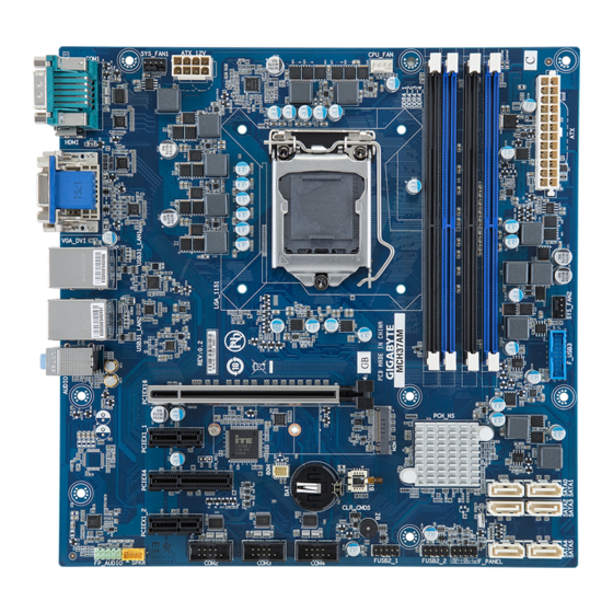
uATX-Q370A (MQ370AM) Quick Reference Guide/ 快速测试参考指南
30
1
2
3
4
27
28 29
31
32
26
25
24
CPU
23
33
22
21
20
DDR4_1
DDR4_2
19
DDR4_3
DDR4_4
18
17
16
15
14
13
11
12
ATX Power/ 电源
1
12
13
24
No.
Pin Define
No.
Pin Define
1
3.3V
13
3.3V
2
3.3V
14
-12V
3
GND
15
GND
4
+5V
16
PS_ON
5
GND
17
GND
6
+5V
18
GND
7
GND
19
GND
8
Power Good
20
-5V
9
5VSB
21
+5V
10
+12V
22
+5V
11
+12V
23
+5V
12
3.3V
24
GND
接口
SATA Connector/SATA
Front Audio Connector/
7
1
7
1
2
No.
Pin Define
1
GND
2
TXP
3
TXN
1
7
1
4
GND
7
1
7
5
RXN
6
RXP
9
10
7
GND
1
7
1
Jumper Se�ngs/ 跳线设置
ATX Mode Select
ATX_SEL
3
AT Mode
2
ATX Mode
1
(Default)
No.
Pin Define
1
Power
2
Signal
3
GND
Clear CMOS
CLR_CMOS
Default
Enable
No.
Code
Descrip�on
5
6
1
AUDIO
Audio connectors
2
USB31_LAN2
GbE LAN port #2 (top) / USB 3.0 port/USB 3.1 Gen2 port (bo�om)
3
USB31_LAN1
GbE LAN port #1 (top) / USB 3.0 ports (bo�om)
4
VGA_DVI
VGA port (top)/DVI-D port (bo�om)
5
HDMI
HDMI 1.4 port
6
COM1
Serial port
7
SYS_FAN1
System fan connector #1
7
8
ATX_12V
8 pin power connector (for CPU)
9
CPU_FAN
CPU fan connector
10
ATX
24 pin main power connector
8
11
SYS_FAN2
System fan connector#2
12
F_USB3
USB 3.0 connector
13
SATA0
SATA 3 6Gb/s connector #0
14
SATA1
SATA 3 6Gb/s connector #1
15
SATA3
SATA 3 6Gb/s connector #3
16
SATA2
SATA 3 6Gb/s connector #2
17
SATA5
SATA 3 6Gb/s connector #5
18
SATA4
SATA 3 6Gb/s connector #4
19
F_PANEL
Front panel header
20
FUSB2_2
USB 2.0 connector #2
9
21
FUSB2_1
USB 2.0 connector #1
22
BAT
Ba�ery socket
23
CLR_CMOS
Clear CMOS jumper
24
COM4
Serial port cable connector #4
25
COM3
Serial port cable connector #3
26
COM2
Serial port cable connector #2
27
FP_AUDIO
Front audio connector
28
PCIEX1_2
PCI Express x1 slot (PCIe x1 Signal)
29
PCIEX4
PCI Express x4 slot (PCIe x4 Signal)
30
ATX_SEL
ATX mode select jumper
31
PCIEX1_1
PCI Express x1 slot (PCIe x1 Signal)
32
PCIEX16
PCI Express x16 slot (PCIe x16 Signal)
10
33
M2M
M.2 slot (PCIe Gen3 x4, Support NGFF-2260/2280, M-Key)
Front Panel Header/
No.
No.
Pin Define
1
2
1
1
GND
2
5
1
2
GND
3
3
GND
4
4
GND
5
5
+12V
6
6
+12V
8
4
7
7
+12V
9
10
8
8
+12V
9
10
前置音频
No.
Pin Define
1
MIC2_L
2
GND
3
MIC2_R
4
FP_AUDIO_DET
1
5
LINE2_R
20
6
GND
7
F_Audio_JD
8
No Pin
9
LINE2_L
10
GND
前面板
CPU/System FAN/ 风扇
4
1
Pin Define
HDD LED+
4
Power LED+
HDD LED-
Power LED-
GND
1
Power Bu�on+
Reset Bu�on
Power Bu�on-
No.
Pin Define
No Connect
1
GND
No Pin
2
+12V
3
Sense
4
Speed Control
USB 3.0 Connector
No.
Pin Define
No.
Pin Define
1
Power
11
Port B_USB2_D+
2
Port A_SSRX-
12
Port B_USB2_D-
3
Port A_SSRX+
13
GND
4
GND
14
Port B_SSTX+
10
5
Port A_SSTX-
15
Port B_SSTX-
11
6
Port A_SSTX+
16
GND
7
GND
17
Port B_SSRX+
8
Port A_USB2_D-
18
Port B_SSRX-
9
Port A_USB2_D+
19
Power
10 OC
20
No Pin
USB 2.0 Header
1
2
No.
Pin Define
No.
Pin Define
1
Power (5V)
6
USB DY+
2
Power (5V)
7
GND
3
USB DX-
8
GND
4
USB DY-
9
No Pin
5
USB DX+
10
No Connect
9
10
COM2 Connector
No.
Pin Define
1
NDCD-
1
2
2
NSIN
3
NSOUT
4
NDTR-
5
GND
6
NDSR-
7
NRTS-
8
NCTS-
9
10
9
NRI-
10
No Pin
Rear I/O Connector/ 后面板接口
1
3
2
4
No.
Desrip�on
1
Serial Port
2
HDMI 1.4 Port
3
VGA Port
4
DVI-D Port
5
GbE Eternet LAN Port #1
6
GbE Eternet LAN Port #2
The HDMI connector is HDCP compliant and supports Dolby True HD and DTS HD
Master Audio formats. It also supports up to 192KHz/24bit 8-channel LPCM audio
output. You can use this port to connect your HDMI-supported monitor. The
maximum supported resolu�on is 4096x2160@24Hz or 2560x1600@60Hz, but the
actual resolu�ons supported are dependent on the monitor being used.
Installing CPU/ 安装 CPU
Memory Popula�on Configura�on/ 安装内存
Memory
Type
2
1
Voltage (V)
Connector
2
Speed (MT/s)
Channels
DIMM Per Channel
DIMM Capacity (GB)
All channels in system run at the fastest common frequency.
UDIMM 2666 two DIMMs per channel (2DPC) is supported when channel is populated with the same UDIMM
memory module.
所有通道模式以最快速率速度运行。
UDIMM 2666支持每通道两个DIMM(2DPC)當每通道安裝相同速率速度的UDIMM内存模块。
M.2 Module
1
2
5
6
9
10
7
7
11
8
No.
Descrip�on
7
USB 3.0 Port x 3
8
USB 3.1 Gen2 Port
9
Line In
10
Line Out
11
Mic In
Speed LED Link/Ac�vity
LED
5 6
10/100/1000 LAN LED:
State
Description
Yellow On
1Gbps data rate
Green On
100Mbps data rate
Off
10Mbps data rate
DDR4
1.2V
UDIMM
2666
2400
1,2
1,2
2,4,6,8,16
System Ba�ery
2
1
Advertisement
Table of Contents

Related Manuals for GIGAIPC uATX-Q370A


Summary of Contents for GIGAIPC uATX-Q370A
- Page 1 (MQ370AM) Quick Reference Guide/ 快速测试参考指南 Code Descrip�on Rear I/O Connector/ 后面板接口 AUDIO Audio connectors USB31_LAN2 GbE LAN port #2 (top) / USB 3.0 port/USB 3.1 Gen2 port (bo�om) USB31_LAN1 GbE LAN port #1 (top) / USB 3.0 ports (bo�om) VGA_DVI VGA port (top)/DVI-D port (bo�om)
- Page 2 The symbol shown below is on the product or on its packaging, which indicates that this product must not be disposed of with other h�ps://www.gigaipc.com natural resources and ensure that it is recycled in a manner that protects human health and the environment.
Need help?
Do you have a question about the uATX-Q370A and is the answer not in the manual?
Questions and answers