Table of Contents

Related Manuals for Sunny Health & Fitness SF-RW5633


Summary of Contents for Sunny Health & Fitness SF-RW5633
- Page 1 AIR ROWING MACHINE SF-RW5633 USER MANUAL IMPORTANT: Read all instructions carefully before using this product. Retain owner’s manual future reference. customer service, please contact: support@sunnyhealthfitness.com...
-
Page 2: Important Safety Information
IMPORTANT SAFETY INFORMATION We thank you for choosing our product. To ensure your safety and health, please use this equipment correctly. It is important to read this entire manual before assembling and using the equipment. Safe and effective use can only be assured if the equipment is assembled, maintained, and used properly. -
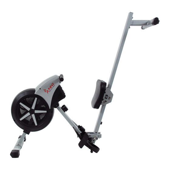
Page 3: Exploded Drawing
EXPLODED DRAWING... -
Page 4: Parts List
PARTS LIST Description Description Handlebar Φ28*1.5*440 Screw M8*20*S6 Washer d8*Φ16*1.5 Handlebar seat 106*40*31 Adjusting screw M6*40*Φ10*2.5 Front stabilizer 4L/R End cap Adjusting U seat 30*10*1.5 Screw ST4.2*19*Φ8 Nut M6*H6*S10 Screw M5*10*Φ10 Fan wheel Inertial axle Φ10*150 Tension control knob Washer d10*Φ20*2 Washer d5*Φ20*1.5 Screw M5*25*Φ8 C clip d10... - Page 5 Bolt M8*100*20*S13 End cap Round magnet Φ15 *7 Nut M8*H7.5*S13 Sliding rail Allen wrench S5 Grommet Φ16 Allen wrench S6 Rear stabilizer Spanner S17-19...
-
Page 6: Hardware Package
HARDWARE PACKAGE #1 M8*20*S6 4PCS #2 d8* 16*1.5 4PCS #52 d8 4PCS #58 M12* 12.5*160*S19 4PCS 10*95*M6*25 1PC #65 d10* 20*2 1PC #66 M6*16*S5 1PC 10*100*105 2PCS... - Page 7 ASSEMBLY INSTRUCTIONS #1 M8*20*S6 2PCS #52 d8 2PCS #2 d8* 16*1.5 2PCS STEP 1: Attach the Front Stabilizer (No. 3) to the Main Frame (No. 49) using 2 Screws (No. 1), 2 Spring Washers (No. 52) and 2 Washers (No. 2). Tighten and secure with Allen Wrench (No.
- Page 8 #58 M12* 12.5*160*S19 4PCS STEP 2: Fix the 2 Bolts (No. 58) into the bottom hole of Main Frame (No. 49) with Spanner (No. C). Insert 2 Bolts (No. 58) through the Pedals (No. 57), into the upper hole of the Main Frame (No. 49), and tighten with Spanner (No.
- Page 9 #1 M8*20*S6 2PCS #2 d8* 16*1.5 2PCS #52 d8 2PCS STEP 3: Insert the Saddle (No. 71) onto the Sliding Rail (No. 79). Attach the Rear Stabilizer (No. 81) to the Sliding Rail (No. 79) using 2 Screws (No. 1), 2 Spring Washers (No.
- Page 10 10*95*M6*25 1PC #65 d10* 20*2 1PC #66 M6*16*S5 1PC 10*100*105 2PCS STEP 4: Connect the Sliding Rail (No. 79) to Main Frame (No. 49). Lift the Main Frame (No. 49) and the Sliding Rail (No. 79) to align the holes. Then insert 2 Pull Pins (No. 67). the Sliding Rail (No.
-
Page 11: Pedal Adjustment
ADJUSTMENT GUIDE PEDAL ADJUSTMENT The pedal strap is adjustable and can be personalized to fit the user’s foot size. To adjust the pedal strap, remove the Velcro end of the strap from the mesh side by pulling it upward then to the left. Once removed, you may increase the opening of the pedal strap by pulling the mesh end up and to the right. -
Page 12: Adjusting The Resistance
ADJUSTMENT GUIDE ADJUSTING THE RESISTANCE Rotate the Tension Control Knob (No. 45) clockwise to increase the level of resistance. Rotate the tension control counter-clockwise to decrease the level of resistance. Level 1 is the lowest and Level 8 is the highest tension. - Page 13 ADJUSTMENT GUIDE Figure A When not in use, you save space folding the Sliding Rail (No. 79). 1. Prop the Main Frame (No. 49) and pull out the 2 Pull Pins (No. 67). Insert 1 Pull Pin (No. 67) into through-hole Saddle Support (No.
- Page 14 EXERCISE METER SPECIFICATIONS: TIME------------------------------------------------------00:00 - 99:59 MIN:SEC COUNT--------------------------------------------------------0 - 9999 STROKES CALORIE-----------------------------------------------------------0 - 9999 KCAL REPS/MIN (STROKES/MIN) ---------------------0 - 9999 STROKES/MIN KEY FUNCTION: MODE: To select the function you want. Hold the key for 4 seconds to reset all function values (total reset). OPERATION PROCEDURES: AUTO ON/OFF: The monitor will turn on when you start rowing or press...
Need help?
Do you have a question about the SF-RW5633 and is the answer not in the manual?
Questions and answers