Table of Contents

Subscribe to Our Youtube Channel
Related Manuals for Sunny Health & Fitness SF-RW5727


Summary of Contents for Sunny Health & Fitness SF-RW5727
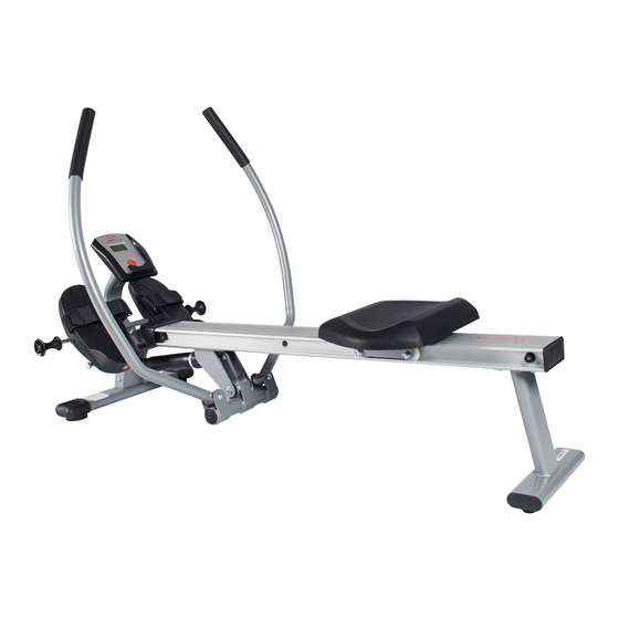
- Page 1 FULL MOTION ROWING MACHINE WITH ALUMINUM SLIDE RAIL SF-RW5727 USER MANUAL IMPORTANT! Read all instructions carefully before using this product. Retain owner’s manual for future reference. For customer service, please contact: support@sunnyhealthfitness.com...
-
Page 2: Important Safety Information
IMPORTANT SAFETY INFORMATION We thank you for choosing our product. To ensure your safety and health, please use this equipment correctly. It is important to read this entire manual before assembling and using the equipment. Safe and effective use can only be achieved if the equipment is assembled, maintained and used properly. -
Page 3: Exploded Drawing
EXPLODED DRAWING HARDWARE PACKAGE #15 Φ10*60 2PCS 2PCS M8*15 13PCS #53 M2*150 2PCS 15PCS φ... -
Page 4: Parts List
PARTS LIST Description Specification Description Specification Front Stabilizer Pedal L Main Frame Pedal R Rear Support Cover Rotating Armrest End Cap Armrest Limit Meter Support Stopper Handlebar Foam Grip L200 Handrail Support Meter L300 Seat Support Trunk Wire F L750 Sliding Rail Sensor Induction Magnet... -
Page 5: Assembly Instructions
ASSEMBLY INSTRUCTIONS STEP 1: Attach the Front Stabilizer (No. 1) to the Main Frame (No. 2) using 2 Screws (No. 43) and 2 Washers (No. 45). Tighten and secure with Allen Wrench (No. 14). STEP 2: Attach the Rear Support (No. 3) onto the Main Frame (No. - Page 6 STEP 4: Insert the Meter (No. 34) into the Meter Support (No. 5). Then attach the Meter (No. 34) onto the Meter Support (No. 5) using 2 Screws (No. 46) and 2 Washers (No. 47). Tighten with Allen Wrench (No. 14). STEP 5: Connect E with F.
- Page 7 STEP 7: Attach the Handlebar (No. 6) into the Rotating Arm Rest (No. 4) using 2 Bolts (No. 15), 2 Washers (No. 45) and 2 Nuts (No. 39). Tighten and secure with Allen Wrench (No. 14) and Spanner (No. 17). STEP 8: Make sure the arrow on the Seat (No.
- Page 8 ADJUSTMENT GUIDE ADJUSTING THE PEDALS The Pedal Straps (No. 48) can be adjusted to the user’s own foot/shoe size. Pull the Pedal Straps (No. 28/29) to adjust the degree of tightness. ADJUSTING THE RESISTANCE To adjust the tension level, turn the Adjustment Knob (C) on the cylinder to the desired level.
- Page 9 EXERCISE MONITOR SPECIFICATIONS: TIME--------------------------------------------------00:00—99:59 MIN/SEC COUNT-----------------------------------------------0—9999 TIMES CALORIES------------------------------------------0—999.9 CAL REPS/MIN-------------------------------------------0—999 TIMES/MIN TOT.CNT---------------------------------------------0—9999 TIMES KEY FUNCTION MODE/SELECT: To select the function you want. Press the key for 4seconds to have all function values reset (total reset). OPERATION PROCEDURES AUTO ON/OFF: The computer turns on when you start pedaling or when you press the button. After 4 minutes without any signal, the power will turn off automatically.
Need help?
Do you have a question about the SF-RW5727 and is the answer not in the manual?
Questions and answers