GeoVision GV-Reader1251 User Manual

GeoVision GV-Reader1251 User Manual

Gv-card reader
Hide thumbs Also See for GV-Reader1251:

Advertisement

Quick Links

GV-Card Reader
User's Manual
Before attempting to connect or operate this product, please
read these instructions carefully and save this manual for future use.
READER-D

Advertisement

Table of Contents
loading
Need help?

Need help?

Do you have a question about the GV-Reader1251 and is the answer not in the manual?

Questions and answers

Summary of Contents for GeoVision GV-Reader1251

  • Page 1 GV-Card Reader User’s Manual Before attempting to connect or operate this product, please read these instructions carefully and save this manual for future use. READER-D...
  • Page 2 GeoVision. Every effort has been made to ensure that the information in this manual is accurate. GeoVision, Inc. makes no expressed or implied warranty of any kind and assumes no responsibility for errors or omissions. No liability is assumed for incidental or consequential damages arising from the use of the information or products contained herein.
  • Page 3: Notice

    Notice Notice for GV-R1352 V2B and GV-R1352 V2C: This device complies with Part 15 of the FCC Rules. Operation is subject to the following two conditions: (1) This device may not cause harmful interference, and (2) This device must accept any interference received, including interference that may cause undesired operation.
  • Page 4: Preface

    Preface Welcome to the GV-Card Reader User’s Manual. This Manual applies to the following GV-Card Readers: Reader Models GV-Reader1251 and 1352 V2 GV-SR1251 GV-RK1352 / R1352 GV-DFR1352 (Rev. B) GV-RKD1352...
  • Page 5: Table Of Contents

    1.2 Installation ....................... 2   1.2.1 Electric Wire ....................2   1.2.2 Switch Setting of GV-Reader1251 / 1352 V2 ..........2   1.2.3 Defining the ID Number of GV-SR1251 by Using GV-Reader Config Utility... 4   1.3 Connecting the Reader to GV-AS Controller ............5  ...
  • Page 6 2.4 Installing GV-R/RK/DFR Config AP ................21   2.5 Overlaying Card Numbers on GV-DVR/NVR Live View ..........22   2.5.1 Defining the ID Number and Setting the Reader to Slave ......22   2.5.2 Adding the Reader to GV-DVR/NVR ............24   2.6 Changing the Default Settings of Beeper and LED ..........25  ...
  • Page 7: Chapter 1 Gv-Reader1251 / 1352 V2 And Gv-Sr1251

    Wiegand and RS-485 outputs that can be connected to any standard access control panel. The LED indicator is controllable by the host system and changes from red to green to indicate access granted. GV-Reader1251 / 1352 V2 / SR1251 also has a host-controllable buzzer.
  • Page 8: Installation

    Yellow Beeper Orange Green LED Light Red Red LED 1.2.2 Switch Setting of GV-Reader1251 / 1352 V2 Electric Wire Switch Default settings are all ON. SW 1 Beeper Control: The default mode for the Beeper Control is the internal control.
  • Page 9 GV-Reader1251 / 1352 V2 and GV-SR1251  SW2-SW3 Green/Red LED Control: The default mode for the Green/Red LED Control is the internal control. The LED is normally red. When a card is read, the LED flashes green. When the setting is “Off”, the Green/Red LED is controlled externally. The external control lines can then be used to operate the LEDs.
  • Page 10: Defining The Id Number Of Gv-Sr1251 By Using Gv-Reader Config Utility

    The settings are sent to the reader. Note: 1. To define the ID number of GV-Reader1251 / 1352 V2, use the switches at the back of the reader. 2. GV-SR1251 only reads UID. Therefore, the Only Read GID option in the GV-...
  • Page 11: Connecting The Reader To Gv-As Controller

    The GV-Reader1251 / 1352 V2 / SR1251 is compatible with any standard access controllers. The following diagrams illustrate how to connect the GV-Reader1251 / 1352 V2 / SR1251 to GV-AS Controller through Wiegand interface or RS-485 interface, and how to connect the GV-Reader1251 / 1352 V2 / SR1251 to third-party access controllers and GV-DVR/NVR.
  • Page 12: Connecting To Gv-As Controller Through Rs-485 Interface

    (Light blue) GV-Reader (Blue) (Red) GV-AS Controller GV-Reader Switch Setting for RS-485 Connection (GV-Reader1251 / 1352 V2 only)  SW4 must be turned OFF. Switch Setting for Connecting Multiple GV-Readers (RS-485) (GV-Reader1251 / 1352  V2 only) Multiple readers can be connected to GV-AS Controller through a single RS-485 cable.
  • Page 13 GV-Reader1251 / 1352 V2 and GV-SR1251 Defining Readers on GV-AS Controller Web Interface After configuring the switch settings of GV-Reader1251 / 1352 V2 or defining the ID number of GV-SR1251 with GV-Reader Config Utility, you need to specify which door each reader controls on the Web interface of GV-AS Controller.
  • Page 14: Connecting To Gv-Dvr/Nvr And Third-Party Access Controllers

    Wiegand interface, connect the reader to GV-DVR/NVR via GV-COM, GV-Hub or GV- NET/IO Card V3.1. Note: The GV-Reader1251 / 1352 V2 / SR1251 is not compatible with the GV-NET Card and the GV-NET/IO Card of versions earlier than V3.
  • Page 15: Overlaying Card Numbers On Gv-Dvr/Nvr Live View

    1352 V2 / SR1251 GV-NET/IO Card Note: 1. For GV-Reader1251 / 1352 V2, make sure to define the ID number and set the reader to slave by configuring the switch settings. For details, see 1.2.2 Switch Setting of GV- Reader1251 / 1352 V2.
  • Page 16: Changing The Default Settings Of Beeper And Led

    GV-R/RK/DFR Config AP. For details, see 2.6.1 Setting up Beeper and LED on GV- R/RK/DFR Config AP. 2. For GV-Reader1251 / 1352 V2, enable external control of the reader’s Beeper and LED by configuring the switch settings. For details, see 1.2.2 Switch Setting.
  • Page 17: Specifications

    150 g / 0.33 lb 125 g / 0.27 Ib 150 g / 0.33 lb Ingress IP66 IP54 IP54 Protection Certification CE, FCC, RoHS For the number of readers supported by a variety of GeoVision controllers, see the compatibility table.
  • Page 18: Chapter 2 Gv-Rk1352 / R1352 / Dfr1352

    Chapter 2 GV-RK1352 / R1352 / DFR1352 GV-RK1352 / R1352 / DFR1352 are card readers capable of recognizing identification cards. GV-RK1352 comes with keypad, allowing it to also recognize PIN codes. GV-DFR1352 is designed to be installed on the door frame. Featured with the Wiegand and RS-485 outputs, the readers can be connected to any standard access control panel.
  • Page 19: Packing List

    GV-RK1352 / R1352 / DFR1352 2.1 Packing List GV-RK1352 1. GV-RK1352 Card Reader 2. Screw x 2 3. Screw Anchor x 2 4. Front Cover Plate x 1 5. Software CD 6. Installation Guide 7. Warranty Card GV-R1352 1. GV-R1352 Card Reader 2.
  • Page 20: Physical Descriptions

    2.2 Physical Descriptions 2.2.1 Electric Wire GV-RK1352 Wire Color Function DC 7.5 ~ 12 V Black Yellow Beeper Orange Green LED Light Red Red LED Green Wiegand Data 0 White Wiegand Data 1 Blue RS-485 + Light Blue RS-485 - Rear View GV-R1352 Wire Color...
  • Page 21 GV-RK1352 / R1352 / DFR1352 GV-DFR1352 Wire Color Function DC 7.5 ~ 12V Black Yellow Beeper Orange Green LED Light Red Red LED Green Wiegand Data 0 White Wiegand Data 1 Blue RS-485 + Light Blue RS-485 - Gray Purple Rear View Brown Install the GV-DFR1352 to the door frame using the supplied screws and screw anchors.
  • Page 22: Keypad (Gv-Rk1352 Only)

    2.2.2 
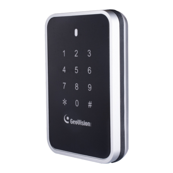
Keypad (GV-RK1352 Only) When accessing an entry using GV-RK1352, you can enter the door’s PIN code on the keypad or present the card and then enter the card’s PIN code on the keypad to be granted access. The access mode is defined on GV-ASManager. 1.
  • Page 23: Connecting The Reader To Gv-As Controller

    You can connect the readers to GV-AS Controllers through Wiegand or RS-485 interface. Note that the connection between the reader and GV-AS Controller varies among controller models. For the number of readers supported by a variety of GeoVision controllers, see the compatibility table.
  • Page 24: Connecting Through Rs-485 Interface

    2.3.2 Connecting through RS-485 Interface The following diagrams use GV-RK1352 and GV-AS810 Controller as an example. Up to eight readers can be connected together to the RS-485 interface on GV-AS810 Controller. Connecting four or less readers to GV-AS810 Controller:  Wire Color Function GV-RK1352 or GV-R1352 (Black)
  • Page 25: Defining Readers On Gv-As Controller Web Interface

    GV-RK1352 / R1352 / DFR1352 2.3.3 Defining Readers on GV-AS Controller Web Interface Since multiple readers can connect to GV-AS Controller using one RS-485 interface, you need to specify which door each reader controls. This section explains how to define readers on the Web interface of GV-AS Controller.
  • Page 26 4. Next to Read Mode, select Read UID or Read GID to set the connected readers to read UID (unique identifier) or GID (GeoVision ID) on GV-AS ID Cards / Key Fobs. If you select Read GID, make sure there are two numbers on your GV-AS ID Cards / Key Fobs as shown below.
  • Page 27: Installing Gv-R/Rk/Dfr Config Ap

    GV-HUB / GV-COM / GV-RK1352 GV-NET/IO Card You can install the Config AP from the GeoVision website. To use a GV-COM, GV-Hub or GV-NET/IO Card V3.1, you also need to install GV-USB Device Driver to enable the device. Downloading from GeoVision Website 1.
  • Page 28: Overlaying Card Numbers On Gv-Dvr/Nvr Live View

    2.5 Overlaying Card Numbers on GV-DVR/NVR Live View You can overlay card numbers recognized at the reader onto a camera channel on GV- DVR/NVR. To overlay card numbers on GV-DVR/NVR channel, the reader needs to be connected to a GV-DVR/NVR through GV-COM, GV-Hub or GV-NET/IO Card V3.1. RS-485 RS-232 (Blue)
  • Page 29 GV-RK1352 / R1352 / DFR1352 2. Select the COM port that is connected to the reader and click Open COM. The red square next to the COM port box should change to blue to indicate the COM port is correct. 3.
  • Page 30: Adding The Reader To Gv-Dvr/Nvr

    2.5.2 Adding the Reader to GV-DVR/NVR 1. In GV-DVR/NVR, click the Configure button, select Accessories, and select GV Wiegand Capture Device Setting. This dialog box appears. 2. Click the New button. This dialog box appears. Type: Select GV-Wiegand Capture.  Device: Type a number and name to help you identify the reader.
  • Page 31: Changing The Default Settings Of Beeper And Led

    GV-RK1352 / R1352 / DFR1352 2.6 Changing the Default Settings of Beeper and LED You can change the default settings of the LED and the beeper by enabling a GV-AS210 / 2110 / 2120 / 410 / 4110 / 810 / 8110 to externally control the LED and Beeper. Through the Web interface of the controller, you can set the controller to trigger the red LED, green LED or beeper when the specified alert event occurs.
  • Page 32 2. Click Open COM. 3. To enable external control of Beeper or LED, select Beeper, Green LED or Red LED. 4. Select Master from the Master / Slave drop-down list. 5. Select an ID number for the reader. Make sure the ID number on the Config AP matches the ID number set on the Extended Reader page of the GV-AS Controller Web interface.
  • Page 33: Wiring The Beeper And Led To Gv-As Controller

    GV-RK1352 / R1352 / DFR1352 2.6.2 Wiring the Beeper and LED to GV-AS Controller To wire the beeper and LED to GV-AS210 / 2110 / 2120 / 410 / 4110 / 810 / 8110, connect the control wires of the reader’s Beeper, Red LED or Green LED to any of the outputs on GV-AS Controller.
  • Page 34: Configuring The Beeper And Led Settings For Each Door/Gate

    After wiring, you also need to go to GV-ASManager to select the alarm conditions that will set off the reader’s beeper. In GV-ASManager, right-click the GV-AS Controller in the device list, click Settings, and click the Door / Gate tab to select the alarm conditions. 2.6.3 Configuring the Beeper and LED Settings for Each Door/Gate After connecting the wires for beeper or LED, specify the conditions to trigger the beeper and LED on the GV-AS210 / 2110 / 2120 / 410 / 4110 / 810 / 8110 Web interface.
  • Page 35: Setting Uid Or Gid On Gv-R/Rk/Dfr Config Ap

    By default, the readers read the UID (unique identifier) on ID cards or key fobs. Using GV- R/RK/DFR Config AP, you can set the GV-RK1352 / R1352 / DFR1352 to read GID (GeoVision ID) on GV-AS ID Cards / Key Fobs instead. Note: ...
  • Page 36 4. Click Setup to apply the setting. The serial number and firmware version of the reader will be automatically detected. To use GID, make sure there are two numbers on your GV-AS ID Cards / Key Fobs as shown below. If there is only one number on your GV-AS ID Cards / Key Fobs, GID is not supported and you must select Unique Identification (UID).
  • Page 37: Firmware Upgrade

    GV-RK1352 / R1352 / DFR1352 2.8 Firmware Upgrade GeoVision will periodically release the updated firmware on the website. The new firmware can be simply loaded into the reader by using Update Utility included in the Software CD. Important Notes before You Start Before you start updating the firmware, please read these important notes: 1.
  • Page 38: Specifications

    Ingress Protection IP66 Certification CE, FCC, RoHS, UL 294, CUL For the number of readers supported by a variety of GeoVision controllers, see the compatibility table. Note: GID ID format is only supported in GV-RK1352 / GV-R1352 / GV-DFR1352 (Rev. B)
  • Page 39: Accessory (Gv-Rk1352 And Gv-R1352 Only)

    GV-RK1352 / R1352 / DFR1352 2.10 Accessory (GV-RK1352 and GV-R1352 Only) Optional accessories can expand the capabilities and versatilities of your GV-RK1352 and GV-R1352. Consult our sales representative for more information. GV-MountA900 is a mounting plate that allows you to attach GV-RK1352 and GV-R1352 to a US single gang power box.
  • Page 40: Chapter 3 Gv-Rkd1352

    Chapter 3 GV-RKD1352 GV-RKD1352 is a card reader with keypad, designed to read PIN codes, identification cards or both. Featured with Wiegand and RS-485 interfaces, GV-RKD1352 can be connected to any standard access control systems. GV-RKD1352 comes with IP65 rated ingress protection suitable for indoor and outdoor applications.
  • Page 41: Physical Descriptions

    3  GV-RKD1352 3.3 Physical Descriptions A. To define the reader’s ID for a daisy chain connection, set up the switches as listed below.
  • Page 42 DESfire Card Support By default, GV-RKD1352 supports Mifare cards. To only support DESFire 13.56MHz cards, turn ON for the switch No 6. Note: GV-DESFire cards contain two types of ID: UID and DES ID. When only DES ID is required, turn on the switch No. 6. Every time when the switch No.
  • Page 43: Installation

    3  GV-RKD1352 3.4 Installation (A) Mount the backplate onto the wall or back box (US standard 120 type). Note DO NOT over tighten the backplate screws during installation to prevent distortion. (B) Connect the wires in accordance with the wiring notes below. (C) Make sure the backplate and the upper cover guide of the reader are aligned.
  • Page 44: Keypad

    Beeper. You can connect these control wires to GV-AS Controller to change the default settings of the LED and Beeper. 3.7 Specifications For details, please see the datasheet. For the number of readers supported by a variety of GeoVision controllers, see the compatibility table.

Table of Contents