Table of Contents
Advertisement
Quick Links
One Technology Way • P.O. Box 9106 • Norwood, MA 02062-9106, U.S.A. • Tel: 781.329.4700 • Fax: 781.461.3113 • www.analog.com
Evaluation Board for the
FEATURES
Full featured evaluation board for the
Uses Cat-5 or SMA as inputs and VGA or SMA as outputs
±5 V operation
EVALUATION KIT CONTENTS
AD8143-EVALZ/AD8145-EVALZ
Instruction guide for user guide download
EQUIPMENT NEEDED
Signal source or video pattern generator and signal analyzer
Power supply: ±5 V/1 A
Cat-5 cable or SMA to SMA cable for inputs
Male to male VGA cable or SMA to SMA cable for outputs
Display or monitor
GENERAL DESCRIPTION
The
AD8143
and
AD8145
are triple, low cost, differential to
single-ended receivers, specifically designed for receiving red,
green, and blue (RGB) signals over a twisted pair cable or
differential printed circuit board (PCB) traces. These products
can also receive any type of analog signal or high speed data
transmission. Two auxiliary comparators with hysteresis are
provided on both products to decode video sync signals encoded
on the received common-mode voltages. These comparators
receive digital signals or can be used as general-purpose
comparators.
The
AD8143
and
AD8145
can be used in conjunction with the
AD8133
and
AD8134
triple differential drivers to provide a
complete, low cost solution for RGB signals over Category-5
(Cat-5) UTP cable applications, including keyboards, videos,
and mouses (KVM).
PLEASE SEE THE LAST PAGE FOR AN IMPORTANT
WARNING AND LEGAL TERMS AND CONDITIONS.
AD8143-EVALZ/AD8145-EVALZ User Guide
AD8143/AD8145
with Comparators
AD8143/AD8145
evaluation board
Rev. 0 | Page 1 of 9
High Speed, Triple Differential Receivers
The excellent common-mode rejection of both the
AD8145
allows the use of low cost, unshielded, twisted pair cables
in noisy environments.
The
AD8143
has a wide power supply range from single +5 V
supply to ±12 V, which allows a wide common-mode range. The
wide common-mode input range of the
integrity in systems where the ground potential is a few volts
different between the driver and receiver ends without using
isolation transformers. The
loop gain is easily set using external resistors.
The
AD8145
can be configured for a differential to single-ended
gain of 1 or 2 by connecting the GAIN_x pin of each channel to
the respective output (gain = 1), or by connecting it to a reference
voltage (gain = 2), which is normally grounded. On the AD8145, a
REF_x input is provided on each channel that allows designers
to level shift the output signals.
Both the
AD8143
and
AD8145
32-lead LFCSP. The
AD8143
industrial temperature range of −40°C to +85°C, while the
can work over the extended industrial temperature range of −40°C
to +105°C. Only the
AD8145
that is qualified for use in automotive applications.
This user guide provides the supporting documents for the
evaluation of the AD8143/AD8145. Consult the
AD8145
data sheets, which provide additional information, when
working with the evaluation board.
UG-862
AD8143
AD8143
maintains signal
AD8143
is stable at a gain of 1. Closed-
are available in a 5 mm × 5 mm,
is rated to work over the extended
has an automotive grade version
AD8143
and
AD8145
and
Advertisement
Table of Contents

Related Manuals for Analog Devices AD8143-EVALZ


Summary of Contents for Analog Devices AD8143-EVALZ
-
Page 1: Features
AD8143-EVALZ/AD8145-EVALZ User Guide UG-862 One Technology Way • P.O. Box 9106 • Norwood, MA 02062-9106, U.S.A. • Tel: 781.329.4700 • Fax: 781.461.3113 • www.analog.com Evaluation Board for the AD8143/AD8145 High Speed, Triple Differential Receivers with Comparators FEATURES The excellent common-mode rejection of both the... -
Page 2: Table Of Contents
UG-862 AD8143-EVALZ/AD8145-EVALZ User Guide TABLE OF CONTENTS Features ....................1 Power Supply ..................4 Evaluation Kit Contents ..............1 Analog Inputs.................4 Equipment Needed ................1 Analog Output ................4 General Description ................. 1 DIS/PD Logic Input ..............4 Revision History ................2 Quick Start Guide ................4 Evaluation Board Photograph and Block Diagram...... -
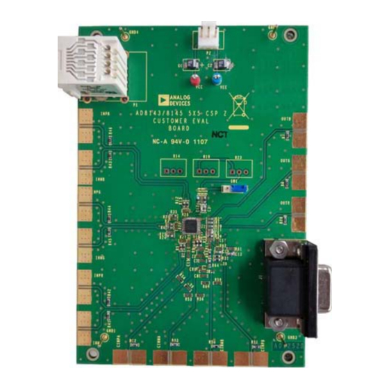
Page 3: Evaluation Board Photograph And Block Diagram
AD8143-EVALZ/AD8145-EVALZ User Guide UG-862 EVALUATION BOARD PHOTOGRAPH AND BLOCK DIAGRAM REF_G OUT_B – GAIN_G OUT_G IN+_G OUT_R – IN–_G AD8145 REF_R COMPB_IN+ – GAIN_R COMPB_IN– – Figure 1. Rev. 0 | Page 3 of 9... -
Page 4: Evaluation Board Hardware
UG-862 AD8143-EVALZ/AD8145-EVALZ User Guide EVALUATION BOARD HARDWARE INTRODUCTION QUICK START GUIDE AD8143-EVALZ/AD8145-EVALZ evaluation board allows To begin, take the following steps: the user to evaluate the AD8143/AD8145 using both SMA and Remove the AD8143/AD8145 from the box. UTP cables. Figure 2 shows the typical bench setup used to Connect +5 V to VCC, −5 V to VEE, and GND to the... - Page 5 AD8143-EVALZ/AD8145-EVALZ User Guide UG-862 DC POWER SUPPLY OSCILLOSCOPE VIDEO DRIVER (AD8147/AD8148) ANALOG INPUTS ANALOG OUTPUTS WAVEFORM/SIGNAL GENERATOR DISPLAY/MONITOR Figure 2. Typical AD8143-EVALZ/AD8145-EVALZ Evaluation Board Setup Rev. 0 | Page 5 of 9...
-
Page 6: Evaluation Board Schematics And Artwork
UG-862 AD8143-EVALZ/AD8145-EVALZ User Guide EVALUATION BOARD SCHEMATICS AND ARTWORK Figure 3. AD8143-EVALZ/AD8145-EVALZ Evaluation Board Schematic Rev. 0 | Page 6 of 9... - Page 7 AD8143-EVALZ/AD8145-EVALZ User Guide UG-862 Figure 4. AD8143-EVALZ/AD8145-EVALZ Evaluation Board, Front View Figure 5. AD8143-EVALZ/AD8145-EVALZ Evaluation Board, Rear View Rev. 0 | Page 7 of 9...
-
Page 8: Bill Of Materials
UG-862 AD8143-EVALZ/AD8145-EVALZ User Guide BILL OF MATERIALS Table 1. AD8143 Bill of Materials Item Reference Designator Description Manufacturer Part Number R6, R7, R18, R24, R29, R32 to R35, 0, R0402 Multicomp 0402WGF0000TCE R39, R41 to R46, R51, R57, R58 R1, R20, R22... - Page 9 By using the evaluation board discussed herein (together with any tools, components documentation or support materials, the “Evaluation Board”), you are agreeing to be bound by the terms and conditions set forth below (“Agreement”) unless you have purchased the Evaluation Board, in which case the Analog Devices Standard Terms and Conditions of Sale shall govern. Do not use the Evaluation Board until you have read and agreed to the Agreement.
Need help?
Do you have a question about the AD8143-EVALZ and is the answer not in the manual?
Questions and answers