Table of Contents
Advertisement
Quick Links
Advertisement
Table of Contents

Subscribe to Our Youtube Channel
Related Manuals for Rohde & Schwarz RT-ZC31


Summary of Contents for Rohde & Schwarz RT-ZC31
- Page 1 ® R&S RT-ZC31 Current Probe User Manual (B1aa2) 1801494902 Version 03...
- Page 2 Rohde & Schwarz GmbH & Co. KG. Trade names are trademarks of the owners. ® 1801.4949.02 | Version 03 | R&S RT-ZC31 ® The following abbreviations are used in this manual: R&S RT-ZC31 is abbreviated as R&S RT-ZC31.
-
Page 3: Table Of Contents
® Contents R&S RT-ZC31 Contents 1 Safety and regulatory information........5 1.1 Safety instructions................5 1.2 Labels on the product................7 1.3 Warning messages in the documentation.......... 8 2 Product description...............9 2.1 Product overview.................. 9 2.2 Key features..................9 2.3 Unpacking and checking..............9 2.4 Description of the Probe.............. - Page 4 ® Contents R&S RT-ZC31 4.3 Typical characteristics................30 4.3.1 Frequency characteristics..............31 4.3.2 Frequency derating curve..............31 4.3.3 Input impedance................... 32 4.3.4 Consumption current................32 4.3.5 Influence of common-mode voltage............33 5 Troubleshooting..............34 5.1 Possible device errors................34 5.2 LED display errors................35 6 Maintenance and service............ 39 6.1 Cleaning....................39...
-
Page 5: Safety And Regulatory Information
® Safety and regulatory information R&S RT-ZC31 Safety instructions Safety and regulatory information The product documentation helps you to use the product safely and efficiently. Follow the instructions provided here and in the Chapter 1.1, "Safety instructions", on page 5. - Page 6 ® Safety and regulatory information R&S RT-ZC31 Safety instructions Reconfigure or adjust the product only as described in the product documentation or the data sheet. Any other modifications can affect safety and are not permitted. Never open the casing of the product. Only service personnel authorized by Rohde &...
-
Page 7: Labels On The Product
® Safety and regulatory information R&S RT-ZC31 Labels on the product Working with current probes When working with current probes, you can measure high-frequency currents or currents that contain high-frequency components. ● Switch off the test circuit while connecting the probe. -
Page 8: Warning Messages In The Documentation
® Safety and regulatory information R&S RT-ZC31 Warning messages in the documentation Table 1-2: Labels regarding product and environment safety Labeling in line with EN 50419 for disposal of electrical and electronic equipment after the product has come to the end of its service life. -
Page 9: Product Description
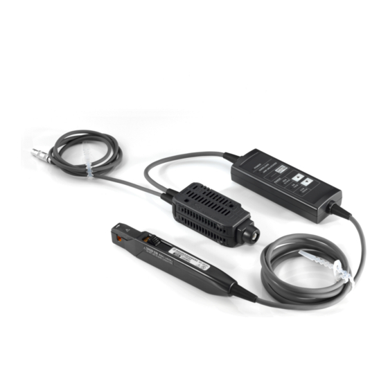
Product description Product overview The R&S RT-ZC31 is a clamp-on current probe that features high current-detec- tion sensitivity and broad frequency band. The probe uses three current ranges to detect current waveforms from a few hundred µA to 50 A. -
Page 10: Description Of The Probe
® Product description R&S RT-ZC31 Description of the Probe 4. Check the equipment for damage. If the delivery is incomplete or equipment is damaged, contact Rohde & Schwarz. Delivery notes The delivery contains the following items: ● User manual ● Carrying case ●... -
Page 11: Termination Unit
® Product description R&S RT-ZC31 Description of the Probe 2.4.2 Termination Unit Figure 2-2: Termination unit overview 1 = Output terminal 2 = Unlock lever 3 = Ventilation holes User Manual 1801.4949.02 ─ 03... - Page 12 ® Product description R&S RT-ZC31 Description of the Probe 4 = Serial number 5 = Power plug 6 = Shell Unlock lever The lock mechanism keeps the clamp closed. Vents The vents are on the sides and bottom. Do not clog them.
-
Page 13: Junction Box (Keys, Leds)
® Product description R&S RT-ZC31 Description of the Probe 2.4.3 Junction Box (Keys, LEDs) 1 = POWER LED 2 = OVERLOAD LED 3 = JAW UNLOCKED LED 4 = DEMAG/AUTO ZERO LED 5 = DEMAG/AUTO ZERO key 6 = RANGE LEDs 7 = ▲(Higher range) key... - Page 14 ® Product description R&S RT-ZC31 Description of the Probe OVERLOAD LED (red light) Shows the overload status of the system. The following states are defined: Color State Flashes three Indicates that demagnetizing or automatic zero adjustment cannot be per- times formed.
-
Page 15: Sensor
® Product description R&S RT-ZC31 Description of the Probe ● The sensor head is unlocked (JAW UNLOCKED LED is lit up) ● During an overload condition (the OVERLOAD LED is flashing) ● When a measured current is detected (Higher range) key / (Lower range) key Switch over to a next higher / lower current range. - Page 16 ® Product description R&S RT-ZC31 Description of the Probe 1 = JAW UNLOCKED indicator 2 = Current direction indicator 3 = Opening lever 4 = Sensor aperture 5 = Jaws 6 = Sensor head JAW UNLOCKED indication If the sensor head is unlocked, you can see this indication on the probe.
-
Page 17: Connecting The Probe
Handling the probe Connecting the probe Handling the probe The R&S RT-ZC31 can withstand a moderate amount of physical and electrical stress. To avoid damage, treat the probe with care: ● Prevent the probe from receiving mechanical shock. ● Avoid strain on the probe cable and route it carefully. Keep the cable away from heat sources, as bare conductors could be exposed if the insulation melts. -
Page 18: Connecting The Probe To The Power Supply
Turn off the power switch at the rear of the R&S RT-ZA13 probe power supply. 3. Connect the power cord. 4. Connect the power plug of the R&S RT-ZC31 to the power receptacle of the R&S RT-ZA13 probe power supply. -
Page 19: Connecting The Probe To The Oscilloscope
Insert the terminator of the R&S RT-ZC31 straight into one of the BNC input connectors of the oscilloscope until it clicks. Take care not to tilt it. -
Page 20: Setting Up And Demagnetizing
● Termination = 1 MΩ ● Manual Gain = 0.1 V/A, 1 V/A or 10 V/A Alternatively, select "Predefined probe" = R&S RT-ZC31 (0.1 V/A)/(1 V/A) /(10 V/A) if this selection is available on the instrument. To disconnect the probe: 1. - Page 21 1. With the waveform measuring instrument input at ground, adjust the waveform to the zero position. 2. Connect the R&S RT-ZC31 current probe to the power supply as described in Chapter 3.2, "Connecting the probe to the power supply", on page 18.
-
Page 22: Connecting The Probe To The Dut
® Connecting the probe R&S RT-ZC31 Connecting the probe to the DUT To halt demagnetization or automatic zero-adjustment in the middle of its execution ► Pull the unlock lever toward you to unlock the upper jaw. After you halt demagnetization or automatic zeroadjustment, re-execute demagnetization and automatic zero-adjustment before taking a measure- ment. - Page 23 ® Connecting the probe R&S RT-ZC31 Connecting the probe to the DUT If the sensor head is not properly closed, accurate measurement is not possi- ble. 5. Check the LEDs on the junction box: a) POWER LED and one of RANGE LEDs light up: no error b) OVERLOAD LED blinks rapidly: the probe has detected measurement cur- rent in excess of the level defined for the current range.
-
Page 24: Disconnecting The Probe From The Dut
® Connecting the probe R&S RT-ZC31 Disconnecting the probe from the DUT Measuring low currents ● To measure DC or low-frequency current, multiple windings may be used to increase relative sensitivity (10 windings multiplies the mea- sured current by a factor of 10). However, in this case, the windings should be made radially, with a diameter of at least 20 cm. -
Page 25: Considerations For Measurements
® Connecting the probe R&S RT-ZC31 Considerations for measurements Considerations for measurements Measurements of continuous input current To avoid damage to the probe when doing measurements of continuous input cur- rent, consider the following: ● The maximum continuous input range is based on heat that is internally gen- erated during measurement. - Page 26 ® Connecting the probe R&S RT-ZC31 Considerations for measurements utive maximum current, electric currents in both sides will heat up the sensor and raise the temperature, thereby causing damage to the sensor. Drift, oscillation, and sound ● Immediately after powering on, the probe may be subject to an appreciable offset drift due to the effect of self-heating.
- Page 27 ® Connecting the probe R&S RT-ZC31 Considerations for measurements At high frequencies, common mode noise may affect measurements taken on the high-voltage side of circuits. If this occurs, reduce the frequency range of the waveform measuring instrument, or clamp onto the low-voltage side of the circuit, as appropriate.
-
Page 28: Features And Characteristics
® Features and characteristics R&S RT-ZC31 Protection mode Features and characteristics How to measure current accurately Retracting and extending the upper jaw can cause an offset voltage of several millivolts. Perform the steps described below to accurately measure a current. - Page 29 ® Features and characteristics R&S RT-ZC31 Protection mode In protection mode, the device cannot correctly measure any current. Moreover, you cannot switch the current ranges. If the device has entered protection mode, recalibrate it because internal components may have been subjected to thermal stress.
-
Page 30: Typical Characteristics
® Features and characteristics R&S RT-ZC31 Typical characteristics Typical characteristics All the characteristics shown in this section are typical for R&S RT-ZC31. User Manual 1801.4949.02 ─ 03... -
Page 31: Frequency Characteristics
® Features and characteristics R&S RT-ZC31 Typical characteristics 4.3.1 Frequency characteristics Figure 4-1: Frequency characteristics 4.3.2 Frequency derating curve Fig. 4-2 shows the derating curves with a sine-wave current input. If the ambient temperature rises or the current being measured contains high-frequency compo- nents, the device temperature rises, and thus its continuously inputtable current value and frequency lowers. -
Page 32: Input Impedance
® Features and characteristics R&S RT-ZC31 Typical characteristics 4.3.3 Input impedance The current probe inserts a load in the circuit to be measured as shown in fig. 4-3. In particular, take this characteristic into account when measuring a high-fre- quency current. -
Page 33: Influence Of Common-Mode Voltage
® Features and characteristics R&S RT-ZC31 Typical characteristics Figure 4-4: Consumption current (with the specified 30 A range ) 4.3.5 Influence of common-mode voltage Fig. 4-5 shows the ratio of a common-mode voltage applied to the conductor being measured and the resulting output voltage. -
Page 34: Troubleshooting
® Troubleshooting R&S RT-ZC31 Possible device errors Troubleshooting If damage is suspected, observe the information in the following chapter before returning for servicing. Possible device errors No waveform is displayed on the host waveform measuring instrument 1. Re-execute demagnetization and automatic zeroadjustment. -
Page 35: Led Display Errors
® Troubleshooting R&S RT-ZC31 LED display errors ● A current exceeding 0.5 A rms has been detected. If you observe this, implement the remedy described in Table 5-1. Then repeat the demagnetization and automatic zero-adjustment, see Chapter 3.4, "Setting up demagnetizing",... - Page 36 ® Troubleshooting R&S RT-ZC31 LED display errors Table 5-1: LED errors Error state Meaning Protection mode A temperature anomaly has been detected and the device has entered protection mode. Remove the device from the conductor being measured immediately. Allow the device to cool under condi- tions of no input and then press the DEMAG/AUTO ZERO key.
- Page 37 ® Troubleshooting R&S RT-ZC31 LED display errors Error state Meaning Demagnetizing / automatic zero- adjustment unavailable This issue occurs when the DEMAG/ AUTO ZERO key is pressed under the circumstances described in the table below. Demagnetization and automatic zero adjustment cannot be performed. Per-...
- Page 38 ® Troubleshooting R&S RT-ZC31 LED display errors Error state Meaning All LEDs blink rapidly. Checksum error An internal CPU malfunction (checksum error) has occurred. Send it to the ser- vice center for repair. No LEDs light up. Malfunction The device has malfunctioned. Send it to the service center for repair.
-
Page 39: Maintenance And Service
® Maintenance and service R&S RT-ZC31 Contacting customer support Maintenance and service If service or calibration is needed, contact your Rohde & Schwarz service center. Return a defective product to the Rohde & Schwarz service center for diagnosis and exchange. -
Page 40: Returning For Servicing
Calibration interval Figure 6-1: QR code to the Rohde & Schwarz support page Returning for servicing Use the original packaging to return your R&S RT-ZC31 to your Rohde & Schwarzservice center. A list of all service centers is available on: www.services.rohde-schwarz.com If you cannot use the original packaging, consider the following: 1. -
Page 41: Storage And Transport
® Maintenance and service R&S RT-ZC31 Disposal Storage and transport Protect the product against dust. Ensure that the environmental conditions, e.g. temperature range and climatic load, meet the values specified in the data sheet. Store the product in a shock-resistant case, e.g. in the shipping case. -
Page 42: S Rt-Za13 Probe Power Supply
® R&S RT-ZA13 probe power supply R&S RT-ZC31 R&S RT-ZA13 probe power supply This unit is a special-purpose power supply for the current probes. You can connect up to four current probes to the power supply. Front view Rear view...
Need help?
Do you have a question about the RT-ZC31 and is the answer not in the manual?
Questions and answers