Table of Contents
Advertisement
Quick Links
Installation - Operation - Maintenance
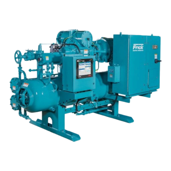
ROTARY SCREW COMPRESSOR UNITS
ALL REFRIGERANTS
60 through 856
Use for 496 – 856 only!
THIS MANUAL CONTAINS RIGGING, ASSEMBLY, START-UP, AND
MAINTENANCE INSTRUCTIONS. READ THOROUGHLY BEFORE
BEGINNING INSTALLATION. FAILURE TO FOLLOW THESE IN-
STRUCTIONS COULD RESULT IN DAMAGE OR IMPROPER OPERA-
TION OF THE UNIT.
MODELS
S70-200 IOM/NOV 2000
File:
SERVICE MANUAL - Section 70
Replaces:
S70-200 IOM/DEC 99
Dist:
3, 3a, 3b, 3c
Advertisement
Table of Contents
Troubleshooting

Related Manuals for Frick RWB II 496


Summary of Contents for Frick RWB II 496
- Page 1 S70-200 IOM/NOV 2000 File: SERVICE MANUAL - Section 70 Replaces: S70-200 IOM/DEC 99 Dist: 3, 3a, 3b, 3c Installation - Operation - Maintenance ROTARY SCREW COMPRESSOR UNITS ALL REFRIGERANTS MODELS 60 through 856 Use for 496 – 856 only! THIS MANUAL CONTAINS RIGGING, ASSEMBLY, START-UP, AND MAINTENANCE INSTRUCTIONS.
-
Page 2: Table Of Contents
S70-200 IOM RWB II ROTARY SCREW COMPRESSOR UNITS Page 2 INSTALLATION - OPERATION - MAINTENANCE 496–856 ONLY! Contents PREFACE ................. 3 COMPRESSOR PRESTART CHECKLIST ..... 22 DESIGN LIMITATIONS ............3 INITIAL START-UP ............23 JOB INSPECTION ............3 INITIAL START-UP PROCEDURE ........23 TRANSIT DAMAGE CLAIMS .......... -
Page 3: Preface
The unit see S90-010 OM ( Quantum panel) or S70-200 OM (Plus data plate containing unit model, serial number and Frick panel). sales order number is mounted on the side of the motor base. -
Page 4: Foundation
When applying screw compressors at high pressures, the for a trouble free installation. Use only the certified general arrangement drawings from Frick Co. to determine the mount- customer must be prepared for package vibration and noise ing foot locations and to allow for recommended clearances higher than the values predicted for normal refrigeration duty. -
Page 5: Motor Mounting
RWB II ROTARY SCREW COMPRESSOR UNITS S70-200 IOM INSTALLATION Page 5 496–856 ONLY! 3. Check that the keys fit the hubs and shafts properly. MOTOR MOUNTING CH COUPLING – The T.B. Woods Elastomeric CH Coupling The following procedure is required only when the motor is is used in most applications up to 600 HP. - Page 6 S70-200 IOM RWB II ROTARY SCREW COMPRESSOR UNITS Page 6 INSTALLATION 496–856 ONLY! 3. Adjust the distance between hub faces as specified in the SPOT HEAT THE HUB as it may cause distortion. Heat in DBZ-B Data Table by sliding the hubs. Key and secure hubs water, oil, or use a SOFT open flame and quickly position to the shafts by tightening setscrews.
-
Page 7: Coupling Alignment Procedure
After final (HOT) alignment has been made and found to be satisfactory for approximately one week, the motor may be dowelled to maintain alignment. NOTE: Frick recommends cold aligning the motor .005" high. This cold misalignment compensates for thermal growth when the unit is at operating temperature. - Page 8 S70-200 IOM RWB II ROTARY SCREW COMPRESSOR UNITS Page 8 INSTALLATION 496–856 ONLY! PARALLEL ALIGNMENT 6. To check parallel alignment, as shown in Fig. 4, reposition dial indicator so the stem is in contact with the rim of the compressor hub, as shown in Fig. 5. Check the dial indicator to be sure that the indicator stem is slightly loaded so as to allow movement in both directions.
-
Page 9: Hot Alignment Of Compressor/Motor
If is within specified tolerance. there is any doubt due to the refrigerant, operating pres- INSTALL COUPLING GUARD BE- sures, or temperatures, refer to Frick Pub. E160-802 SPC FORE OPERATING COMPRESSOR. for guidance. OIL CHARGE... -
Page 10: Oil Heater(S)
Should additional heating capacity be re- quired because of low ambient, contact Frick Company. The heater(s) is energized only when the unit is not in operation. Do not energize the heater(s) when there is no oil in the unit, the heat- er(s) will burn out. -
Page 11: Water-Cooled Oil Cooling (Optional)
RWB II ROTARY SCREW COMPRESSOR UNITS S70-200 IOM INSTALLATION Page 11 496–856 ONLY! 2. A shell and tube oil cooler with: WATER-COOLED OIL COOLING (OPTIONAL) Shell Side: Oil 400 lb. design The shell and tube type water-cooled oil cooler is mounted Tube Side: Refrigerant 400 lb. - Page 12 S70-200 IOM RWB II ROTARY SCREW COMPRESSOR UNITS Page 12 INSTALLATION 496–856 ONLY! OIL TEMPERATURE CONTROL - Oil temperature will gen- shell side (oil side) safety valve directly into the oil separa- erally run about 15 - 35 F above condensing temperature. tor, as shown in the P &...
-
Page 13: Economizer - High Stage (Optional)
RWB II ROTARY SCREW COMPRESSOR UNITS S70-200 IOM INSTALLATION Page 13 496–856 ONLY! The recommended economizer systems are shown below. ECONOMIZER - HIGH STAGE (OPTIONAL) Notice that in all systems there should be a strainer (STR) The economizer option provides an increase in system ca- and a check valve (VCK) between the economizer vessel pacity and efficiency by subcooling liquid from the condenser and the economizer port on the compressor. -
Page 14: Economizer Load Balancing
This will direct all the flash vapor to the other loaded noisy power lines are encountered, a regulating control trans- compressors. former should be considered. Contact FRICK for assistance. 2. A dual-setpoint back-pressure regulator valve can be used 5. For customer-supplied across-the-line starters, a shunt- in each of the individual economizer vapor lines. -
Page 15: Control Power Regulator
(see illus- SOLA #63-23-112-4, 120 VA, 60 HZ tration in either S90-010 M ( Quantum panel) or S70-200 SHOWN HERE- CONSULT FRICK OM (Plus panel) must be moved from OFF (pins 1-2) to ON FOR OTHER VOLTAGES/HZ (pins 2-3). -
Page 16: Operation And Start-Up Instructions
OPERATION and START-UP noise transmission. INSTRUCTIONS COMPRESSOR ROTATION IS The Frick RWB II Rotary Screw Compressor Unit is an inte- CLOCKWISE WHEN FACING THE grated system consisting of six major subsystems: COMPRESSOR DRIVE SHAFT. THE COMPRESSOR SHOULD NEVER BE OPERATED IN RE- 1. -
Page 17: Cycling Full-Lube Oil System
RWB II ROTARY SCREW COMPRESSOR UNITS S70-200 IOM OPERATION Page 17 496–856 ONLY! pressure differential has been reached between suction above 10 PSI, the alarm can be cleared. The pump will con- and discharge, the PRELUBE pump will shut down and the tinue to run until the discharge pressure is 55 PSI over suc- lubrication oil will be supplied by the pressure differential. -
Page 18: Compressor Hydraulic System
S70-200 IOM RWB II ROTARY SCREW COMPRESSOR UNITS Page 18 OPERATION 496–856 ONLY! Higher operating pressures will slow the compressor un- COMPRESSOR HYDRAULIC SYSTEM loading response time. Unloading response time can be in- creased by closing valve 1 (oil manifold pressure) and open- The compressor hydraulic system moves the movable slide ing valve 2 to compressor suction pressure. - Page 19 CLOSE VALVE 1 HIGH STAGE OPEN VALVE 2 CLOSE VALVE 2 BOOSTER OPEN VALVE 1 FROM FRICK OIL FILTER SOLENOID VALVE FUNCTION: YY1 ENERGIZE UNLOAD SLIDE VALVE YY2 ENERGIZE LOAD SLIDE VALVE YY3 ENERGIZE INCREASE VOLUME RATIO YY4 ENERGIZE DECREASE VOLUME RATIO...
-
Page 20: Compressor Oil Cooling Systems
(PDCV) to prevent migration of high pres- sure gas during shutdown. A Frick-installed timer limits the 4. Monitor the oil temperature of the compressor. It the oil high pressure gas to only thirty seconds duration, since in- temperature rises above 150°F, open back-pressure bleed... -
Page 21: Suction Check Valve
On systems located outdoors or in unheated buildings where Frick provides a power assist kit consisting of a mounted the ambient temperature could drop below +40°F, insulat- and wired solenoid valve and timer on all RWB II booster ing and/or heat tracing of the compressor lube oil systems compressors. -
Page 22: Compressor Prestart Checklist
The following items MUST be checked and completed by the installer prior to the arrival of the Frick Field Service Supervisor. Details on the checklist can be found in the IOM. Certain items on this checklist will be reverified by the Frick Field Service Supervisor prior to the actual start-up. -
Page 23: Initial Start-Up
Initial start-up must be performed under the supervision of 1. Confirm system conditions permit starting the compressor. a FRICK authorized start-up representative to prevent void- ing the compressor warranty. Prior to the start-up, the prestart 2. Press the [RUN] key. -
Page 24: General Information
S70-200 IOM RWB II ROTARY SCREW COMPRESSOR UNITS Page 24 MAINTENANCE 496–856 ONLY! GENERAL INFORMATION This section provides instructions for normal maintenance, 1. IF UNIT IS RUNNING, PRESS STOP KEY. a recommended maintenance program, troubleshooting and correction guides, and typical P and I diagrams. For typical 2. -
Page 25: General Instructions For Replacing Compressor Unit Components
Oil entrained refrigerant may vapor- ize, causing a separator pressure 5. Flush the canister with clean Frick refrigeration oil; wipe increase. Repeat venting and re- dry with a clean, lint-free cloth; and replace the plug. covery procedure, if necessary. -
Page 26: Strainer - Full Lube Oil Pump
4. Remove capscrews securing strainer cover, strainer cover, gasket and element. Retain gasket. Use of filter elements other than Frick must be approved in writing 5. Wash element in solvent and blow clean with air. by Frick engineering or warranty claim may be denied. -
Page 27: Changing Oil
Refer to the table in the OIL CHARGE sec- tion for approximate oil charge quantities. 2. Only use Frick oil filters or those approved by Frick for your application. 12. Open the suction and discharge service valves, and also the liquid injection and economizer service valves, if appli- 3. -
Page 28: Operating Log
S70-200 IOM RWB II ROTARY SCREW COMPRESSOR UNITS Page 28 MAINTENANCE 496–856 ONLY! LUBRICATION SCHEDULE / INSTRUCTIONS • LUBRICATE BEARINGS WITH POWER IN SYNC. FRAME SERVICE CYCLE* - BALL BEARING** THE OFF CONDITION. • CLEAR AND CLEAN THE GREASE FITTINGS SERIES 8 HR/DAY OPERATION 24 HR/DAY OPERATION... -
Page 29: Maintenance Schedule
RWB II ROTARY SCREW COMPRESSOR UNITS S70-200 IOM MAINTENANCE Page 29 496–856 ONLY! MAINTENANCE SCHEDULE This schedule should be followed to ensure trouble-free operation of the compressor unit. HOURS OPERATION (MAXIMUM) MAINTENANCE CHANGE OIL As directed by oil analysis OIL ANALYSIS Then every 6 months CHANGE FILTERS CLEAN OIL... -
Page 30: Troubleshooting Guide
S70-200 IOM RWB II ROTARY SCREW COMPRESSOR UNITS Page 30 MAINTENANCE 496–856 ONLY! 8. Refrigerant underfeed or overfeed to evaporators. TROUBLESHOOTING GUIDE 9. Blocked tubes in water cooled oil cooler from high min- Successful problem solving requires an organized approach eral content of water. -
Page 31: Pressure Transducers - Testing
RWB II ROTARY SCREW COMPRESSOR UNITS S70-200 IOM MAINTENANCE Page 31 496–856 ONLY! 12. Measure the voltage of PE-3 on connector P4 (termi- PRESSURE TRANSDUCERS - TESTING nals WHT and BLK) on the SBC. Pressure transducers are located on a covered manifold 13. -
Page 32: Position Potentiometer Replacement And Adjustment
S70-200 IOM RWB II ROTARY SCREW COMPRESSOR UNITS Page 32 MAINTENANCE 496–856 ONLY! PRESSURE TRANSDUCER CONVERSION DATA 100 psi 200 psi 300 psi 500 psi Sensor Range - PSIG* Range - PSIG* Range - PSIG* Range - PSIG* Voltage high high high high... -
Page 33: Volumizer® Potentiometer
RWB II ROTARY SCREW COMPRESSOR UNITS S70-200 IOM MAINTENANCE Page 33 496–856 ONLY! 7. Adjustment: VOLUMIZER ® POTENTIOMETER ROUGH ADJUSTMENT is made with the slide valve fully REPLACEMENT AND ADJUSTMENT unloaded and the control power off. Remove connector P5. With a digital voltmeter, measure the resistance across the ®... -
Page 34: Troubleshooting The Rwb Ii Compressor
Unloader piston stuck. Contact Frick Factor or Frick Co. for assistance. Slipper seals worn out or damaged. Contact Frick Factor or Frick Co. for assistance. NOTE: Troubleshooting the compressor is limited to identifying the probable cause. If a mechanical problem is suspected contact the Service Department, Frick Company. -
Page 35: Hydraulic System
SLIDE STOP WILL NOT FUNCTION Solenoid coils may be burned out, replace. EITHER DIRECTION Solenoid service valves may be closed, open. Manually actuate solenoid. If slide stop will not move mechanical problems are indicated. Consult Frick factor or Frick Co. -
Page 36: Prelube Pump System
S70-200 IOM RWB II ROTARY SCREW COMPRESSOR UNITS Page 36 MAINTENANCE 496–856 ONLY! TROUBLESHOOTING THE PRELUBE PUMP SYSTEM SYMPTOM PROBABLE CAUSES and CORRECTIONS PRELUBE PUMP WILL NOT Filter cartridge in filter F-2 may be clogged, replace. GENERATE SUFFICIENT OIL PRESSURE TO ALLOW Clean strainer before prelube pump inlet. -
Page 37: Liquid Injection Oil Cooling System
RWB II ROTARY SCREW COMPRESSOR UNITS S70-200 IOM MAINTENANCE Page 37 496–856 ONLY! TROUBLESHOOTING THE LIQUID INJECTION OIL COOLING SYSTEM SYMPTOM PROBABLE CAUSES and CORRECTIONS HIGH OIL TEMPERATURE Insufficient liquid supply, check receiver level and pressure drop at injection solenoid. Equalizer pressure too high, lower (through 480 only). -
Page 38: Thermal Expansion Valves
S70-200 IOM RWB II ROTARY SCREW COMPRESSOR UNITS Page 38 MAINTENANCE 496–856 ONLY! JORDAN TEMPERATURE REGULATOR VALVE THERMAL EXPANSION VALVES (MODELS 496 – 856) In situations where system load conditions increase or de- crease over extended periods of time and the liquid injec- tion thermal expansion valve is not adequate for the new conditions, an improvement in valve performance may be achieved by increasing or decreasing discharge tube size. -
Page 39: Jordan Temperature Regulator Valve
RWB II ROTARY SCREW COMPRESSOR UNITS S70-200 IOM MAINTENANCE Page 39 496–856 ONLY! R-22 TX VALVE SIZES BALANCE PISTON PRESSURE REGULATOR TX VALVE MODE FPT CONNECTION 954A0014H01 PRESSURE-REGULATING VALVE (A4ALE) FROM HVE - 2-/1/2 TO SB-2 COMPRESSOR HVE - 5-1/2 COMPRESSOR DISCHARGE OR PORT... - Page 40 S70-200 IOM RWB II ROTARY SCREW COMPRESSOR UNITS Page 40 MAINTENANCE 496–856 ONLY! P & I DIAGRAM, 496 – 856, HORIZONTAL SEPARATOR BPCO HIGH STAGE OR SWING DUTY ONLY CONNECT TO SC-6 BOOSTER SUCTION GAS NOTE: VALVE BODY ASSEMBLY CONSISTS OF ONLY TO THE COMPR SUCTION STRAINER &...
- Page 41 RWB II ROTARY SCREW COMPRESSOR UNITS S70-200 IOM MAINTENANCE Page 41 496–856 ONLY! P & I DIAGRAM, 496 – 856, VERTICAL SEPARATOR (w/prelube oil pump)
-
Page 42: P & I Diagram, 60 - 270
S70-200 IOM RWB II ROTARY SCREW COMPRESSOR UNITS Page 42 MAINTENANCE 496–856 ONLY! P & I DIAGRAM, 496 – 856 V-310 V-310 SEPARATOR SEPARATOR FROM OIL FROM OIL COOLER COOLER SAFETY VALVE SAFETY VALVE LSLL LSLL 1 PUMPOUT 1 PUMPOUT CV-4 CV-4 HTR-1 / 500W... - Page 43 RWB II ROTARY SCREW COMPRESSOR UNITS S70-200 IOM MAINTENANCE Page 43 496–856 ONLY! P & I DIAGRAM, 496 – 856 HV-2 HV-1 "B" LIQUID REFRIGERANT FROM THE RECEIVER SL-1 "C" HIGH PRESSURE LOCATE DRAIN AT LOW POINT OF PIPING RWB6LI1 LIQUID INJECTION, SINGLE PORT HV-2 SUCTION...
- Page 44 S70-200 IOM RWB II ROTARY SCREW COMPRESSOR UNITS Page 44 PROPER INSTALLATION OF ELECTRONIC EQUIPMENT 496–856 ONLY! PROPER INSTALLATION OF ELECTRONIC EQUIPMENT IN AN INDUSTRIAL ENVIRONMENT to provide a “clean” separate source voltage in order to In today’s refrigeration plants, electronic controls have found prevent EMI, from other equipment in the plant, from inter- their way into almost every aspect of refrigeration control.
- Page 45 RWB II ROTARY SCREW COMPRESSOR UNITS S70-200 IOM PROPER INSTALLATION OF ELECTRONIC EQUIPMENT Page 45 496–856 ONLY! Never run any wires through an electronic control panel GROUNDING that do not relate to the function of the panel. Electronic control panels should never be used as a junction box. Grounding is the most important factor for successful op- These wires may be carrying large transients that will inter- eration and is also the most overlooked.
- Page 46 S70-200 IOM RWB II ROTARY SCREW COMPRESSOR UNITS Page 46 PROPER INSTALLATION OF ELECTRONIC EQUIPMENT 496–856 ONLY! PLANT SUPPLY Never add relays, starters, timers, transformers, etc. in- TRANSFORMER side an electronic control panel without first contacting 3-PHASE the manufacturer. Contact arcing and EMI emitted from these devices can interfere with the electronics.
- Page 47 RWB II ROTARY SCREW COMPRESSOR UNITS S70-200 IOM MAINTENANCE Page 47 496–856 ONLY! OPERATING LOG SHEET...
-
Page 48: Proper Installation Of Electronic Equipment
S70-200 IOM RWB II ROTARY SCREW COMPRESSOR UNITS Page 48 MAINTENANCE 496–856 ONLY! RECOMMENDED SPARE PARTS - CURRENT DESIGN ITEM DESCRIPTION QTY. MODELS ITEM NUMBER Temperature Probe (TE-1—4) 640A0035H01 Transducer, Pressure, 0—200 PSIA (PE-4) 333Q0001345 Transducer, Pressure, 0—500 PSIA (PE-1—3) 111Q0280887 Potentiometer, Slide Stop 111Q0041148...
Need help?
Do you have a question about the RWB II 496 and is the answer not in the manual?
Questions and answers