Table of Contents
Advertisement
Quick Links
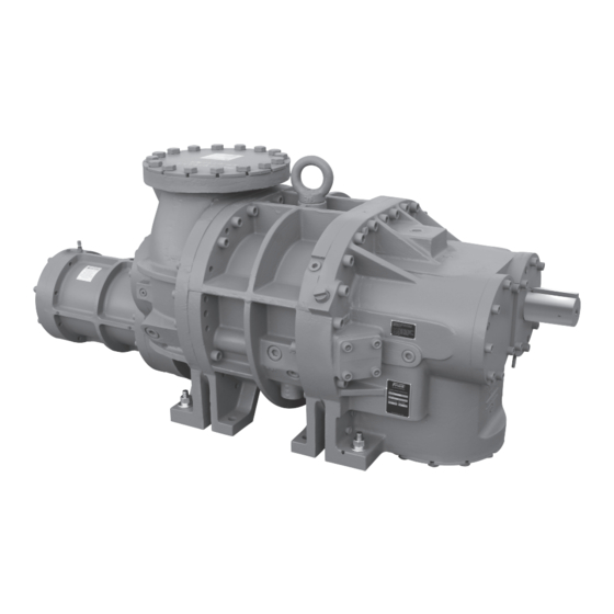
Rotary Screw Compressor
Models TDS_163 - TDS_355
This manual contains installation, operation, and maintenance
instructions. Read thoroughly before beginning installation. Failure
to follow these instructions may result in personal injury or death,
damage to the unit, or incorrect operation.
Check www.FrickCold.com for the latest version of this publication.
Form 070.250-IOM1 (NOV 2013)
Installation – Operation – Maintenance
File:
Service Manual – Section 070
Replaces:
Nothing
Distribution: 3, 3a, 3b, 3c
Revised:
April 2016, p. 2, 8, 16
October 31, 2022
TDS_
Advertisement
Table of Contents
Troubleshooting


Need help?
Do you have a question about the TDS Series and is the answer not in the manual?
Questions and answers