Table of Contents
Advertisement
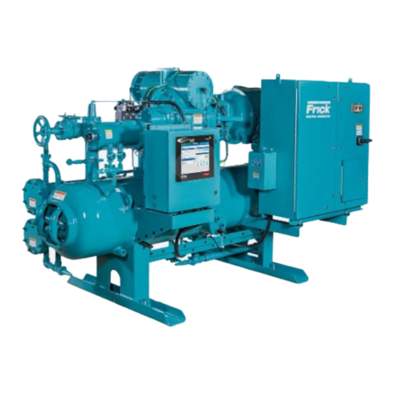
Installation - Operation - Maintenance
ROTARY SCREW COMPRESSOR UNITS
ALL REFRIGERANTS
496 through 1080
THIS MANUAL CONTAINS RIGGING, ASSEMBLY, START-UP, AND
MAINTENANCE INSTRUCTIONS. READ THOROUGHLY BEFORE
BEGINNING INSTALLATION. FAILURE TO FOLLOW THESE
INSTRUCTIONS COULD RESULT IN DAMAGE OR IMPROPER
OPERATION OF THE UNIT.
MODELS
S70-210 IOM/OCT 2004
File:
SERVICE MANUAL - Section 70
Replaces:
S70-200 IOM/DEC 99
Dist:
3, 3a, 3b, 3c
Advertisement
Table of Contents
Troubleshooting

Related Manuals for Frick RWB II 496


Summary of Contents for Frick RWB II 496
- Page 1 S70-210 IOM/OCT 2004 File: SERVICE MANUAL - Section 70 Replaces: S70-200 IOM/DEC 99 Dist: 3, 3a, 3b, 3c Installation - Operation - Maintenance ROTARY SCREW COMPRESSOR UNITS ALL REFRIGERANTS MODELS 496 through 1080 THIS MANUAL CONTAINS RIGGING, ASSEMBLY, START-UP, AND MAINTENANCE INSTRUCTIONS.
-
Page 2: Table Of Contents
S70-210 IOM RWB II ROTARY SCREW COMPRESSOR UNITS Page 2 INSTALLATION - OPERATION - MAINTENANCE Contents PREFACE ................3 POWER ASSIST KIT............21 DESIGN LIMITATIONS ............3 INITIAL START-UP ............22 JOB INSPECTION............. 3 INITIAL START-UP PROCEDURE ........22 TRANSIT DAMAGE CLAIMS ..........3 NORMAL START-UP PROCEDURE ....... -
Page 3: Preface
DESIGN LIMITATIONS The compressor units are designed for operation within the pressure and temperature limits as shown in Frick Pub. E70-200 SED. JOB INSPECTION Immediately upon arrival examine all crates, boxes and exposed compressor and component surfaces for damage. -
Page 4: Installation
Use only the certified When applying screw compressors at high pressures, the general arrangement drawings from Frick to determine the customer must be prepared for package vibration and noise mounting foot locations and to allow for recommended clear- higher than the values predicted for normal refrigeration duty. -
Page 5: Motor Mounting
RWB II ROTARY SCREW COMPRESSOR UNITS S70-210 IOM INSTALLATION Page 5 MOTOR MOUNTING DBZ-B COUPLING – The Thomas DBZ-B coupling is used on applications above 600 HP and with sleeve bearing mo- The following procedure is required only when the motor is tors that do not have axial end float constraint. - Page 6 S70-210 IOM RWB II ROTARY SCREW COMPRESSOR UNITS Page 6 INSTALLATION SERIES 52 COUPLING – The Thomas Series 52 coupling is If the motor is coupled to the compressor using a fixed-end- also used on applications above 600 HP. It has two drive hubs, play coupling and the motor is not properly centered, the a center spool, and disc packs which are bolted between the additional thrust loads will be transmitted to the compressor...
-
Page 7: Coupling Alignment Procedure
After final (HOT) alignment has been made and found to be satisfactory for approximately one week, the motor may be dowelled to maintain alignment. NOTE: Frick recommends cold aligning the motor .005" high. This cold misalignment compensates for thermal growth when the unit is at operating temperature. - Page 8 S70-210 IOM RWB II ROTARY SCREW COMPRESSOR UNITS Page 8 INSTALLATION PARALLEL ALIGNMENT 6. To check parallel alignment, as shown in Figure 4, reposi- tion dial indicator so the stem is in contact with the rim of the compressor hub, as shown in Figure 5. Check the dial indicator to be sure that the indicator stem is slightly loaded so as to allow movement in both directions.
-
Page 9: Hot Alignment Of Compressor/Motor
If there is any doubt due to the refrigerant, operating pres- rises .005" between its hot and cold state, .005" of shims sures, or temperatures, refer to Frick Pub. E160-802 SPC should be removed from under the motor. for guidance. -
Page 10: Oil Heater(S)
Should additional heating capacity be required because of low ambient, contact Frick.The heater(s) is energized only when the unit is not in operation. Do not energize the heater(s) when there is no oil in the unit, the heat- er(s) will burn out. -
Page 11: Water-Cooled Oil Cooling (Optional)
Frick P&I diagram and arrangement drawings. The water criteria are possible. supply must be sufficient to meet the required flow. - Page 12 S70-210 IOM RWB II ROTARY SCREW COMPRESSOR UNITS Page 12 INSTALLATION OIL TEMPERATURE CONTROL - Oil temperature will gen- shell side (oil side) safety valve directly into the oil separator, erally run about 15 - 35°F above condensing temperature. as shown in the P & I diagrams section. In many cases, an oil temperature control is not required if This arrangement uses a special UV stamped safety valve condensing temperature is above 65°F as oil temperature...
-
Page 13: Economizer - High Stage (Optional)
RWB II ROTARY SCREW COMPRESSOR UNITS S70-210 IOM INSTALLATION Page 13 ECONOMIZER - HIGH STAGE (OPTIONAL) The recommended economizer systems are shown below. Notice that in all systems there should be a strainer (STR) The economizer option provides an increase in system ca- and a check valve (VCK) between the economizer vessel pacity and efficiency by subcooling liquid from the condenser and the economizer port on the compressor. -
Page 14: Electrical
Page 14 INSTALLATION For refrigeration plants using a Packaged Refrigerant Recir- particularly in booster applications. Contact FRICK if assistance is required. culation (PRR) unit and a direct expansion (DX) economizer system it is necessary to operate the liquid feed solenoid on 2. -
Page 15: Current Transformer (Ct) Ratios
120/240 V. IN, 120 V. OUT – – – 1200:5 1000:5 200:5 200:5 SOLA #63-23-112-4, 120 VA, 60 HZ – – – – 1000:5 300:5 200:5 SHOWN HERE- CONSULT FRICK – – – – 1200:5 300:5 200:5 FOR OTHER VOLTAGES/HZ 1000 – – –... -
Page 16: Operation
OPERATION and START-UP INSTRUCTIONS COMPRESSOR DRIVE SHAFT. THE COMPRESSOR SHOULD NEVER BE OPERATED IN REVERSE ROTA- The Frick RWB II Rotary Screw Compressor Unit is an inte- TION AS BEARING DAMAGE WILL RESULT WHICH CAN grated system consisting of six major subsystems: CAUSE CATASTROPHIC FAILURE OF THE COMPRES- SOR. -
Page 17: Cycling Full-Lube Oil System
RWB II ROTARY SCREW COMPRESSOR UNITS S70-210 IOM OPERATION Page 17 be supplied by the pressure differential. If after five minutes NOTE: For alarm and shutdown or cutout values, see S90-010 O (Quantum) or S70-200 OM (Plus). 25 PSID has not been reached, the unit will shutdown on DCO cutout. -
Page 18: Compressor Hydraulic System
S70-210 IOM RWB II ROTARY SCREW COMPRESSOR UNITS Page 18 OPERATION COMPRESSOR HYDRAULIC SYSTEM NOTE: High Stage Operation: An alternative piping ar- rangement has been provided to increase slide valve The compressor hydraulic system moves the movable slide response time during high stage operation. valve (MSV) to load and unload the compressor. -
Page 19: Compressor Oil Cooling Systems
A solenoid valve SV6 is installed before the differential the following ranges for R-717 and R-22: pressure control valve (PDCV) to prevent migration of high pressure gas during shutdown. A Frick-installed timer limits Liquid Injection External* the high pressure gas to only thirty seconds duration, since... -
Page 20: Liquid Injection Adjustment Procedure
S70-210 IOM RWB II ROTARY SCREW COMPRESSOR UNITS Page 20 OPERATION Solenoid valve SV5 is energized by the microprocessor when to raise the oil temperature, and counter-clockwise to lower the temperature sensor, installed in the oil manifold, exceeds the oil temperature. After the adjustment has been made the LICO set point. -
Page 21: Suction Check Valve
Also it is important to close HV-2, if the oil pump is to be run for long periods of time with the compressor stopped, to avoid Frick provides a power assist kit consisting of a mounted oil being pumped up the suction line. -
Page 22: Initial Start-Up
Initial start-up must be performed under the supervision of a design conditions creates a potential hazard. FRICK authorized start-up representative to prevent voiding 3. Rotate and lubricate motor bearings according to the compressor warranty. Prior to the start-up, the prestart manufacturer’s recommendations PRIOR to start-up as... -
Page 23: Maintenance
RWB II ROTARY SCREW COMPRESSOR UNITS S70-210 IOM MAINTENANCE Page 23 GENERAL INFORMATION This section provides instructions for normal maintenance, a recommended maintenance program, troubleshooting and 1. IF UNIT IS RUNNING, PRESS STOP KEY. correction guides, and typical P and I diagrams. For typical 2. -
Page 24: General Instructions For Replacing Compressor Unit Components
4. SLOWLY vent separator to low-side system pressure us- 5. Flush the canister with clean Frick refrigeration oil; wipe ing the bypass line on the suction trap. NOTE: Recover or dry with a clean, lint-free cloth; and replace the plug. -
Page 25: Strainer - Full Lube Oil Pump
Use of filter elements other than pump motor starters. Frick may cause warranty claim 2. Close strainer inlet service valve. may to be denied. When changing the coalescer filter element(s) it is recom- 3. -
Page 26: Recommended Maintenance Program
Using 4. Vibration readings can be influenced by other equipment operat- a pressure-type oil pump and recommended Frick oil, open ing in the vicinity or connected to the same piping as the unit. -
Page 27: Operating Log
RWB II ROTARY SCREW COMPRESSOR UNITS S70-210 IOM MAINTENANCE Page 27 OPERATING LOG NLGI Grease Compatibility Chart The use of an operating log as included in this manual (see Table of Contents) permits thorough analysis of the opera- tion of a refrigeration system by those responsible for its maintenance and servicing. -
Page 28: Troubleshooting Guide
S70-210 IOM RWB II ROTARY SCREW COMPRESSOR UNITS Page 28 MAINTENANCE TROUBLESHOOTING GUIDE for the compressor unit in that particular system. The following list of abnormal system conditions can cause Successful problem solving requires an organized approach abnormal operation of the RWB II compressor unit: to define the problem, identify the cause, and make the proper correction. -
Page 29: Pressure Transducers - Testing
RWB II ROTARY SCREW COMPRESSOR UNITS S70-210 IOM MAINTENANCE Page 29 PRESSURE TRANSDUCERS - TESTING 11. Since the discharge pressure, PE-3, cannot be closed off from its sensing point (code requirements), close all transduc- Pressure transducers are located on a covered manifold ers from atmosphere and open them to their sensing points directly behind the microprocessor console See Figure 26. - Page 30 S70-210 IOM RWB II ROTARY SCREW COMPRESSOR UNITS Page 30 MAINTENANCE PRESSURE TRANSDUCER CONVERSION DATA 100 psi 200 psi 300 psi 500 psi Sensor Range - PSIG* Range - PSIG* Range - PSIG* Range - PSIG* Voltage high high high high 29.92"...
-
Page 31: Position Potentiometer Replacement And Adjustment
RWB II ROTARY SCREW COMPRESSOR UNITS S70-210 IOM MAINTENANCE Page 31 SV POSITION POTENTIOMETER VOLUMIZER POTENTIOMETER ® REPLACEMENT AND ADJUSTMENT REPLACEMENT The Slide Valve Position potentiometer is located on the end The VOLUMIZER potentiometer is located under a cover ® of the compressor unloader cylinder. -
Page 32: Troubleshooting The Rwb Ii Compressor
Unloader piston stuck. Contact Frick Factor or Frick for assistance. Slipper seals worn out or damaged. Contact Frick Factor or Frick for assistance. NOTE: Troubleshooting the compressor is limited to identifying the probable cause. If a mechanical problem is suspected contact the Service Department, Frick. -
Page 33: Hydraulic System
SLIDE STOP WILL NOT FUNCTION Solenoid coils may be burned out, replace. EITHER DIRECTION Solenoid service valves may be closed, open. Manually actuate solenoid. If slide stop will not move mechanical problems are indicated. Consult Frick factor or Frick. -
Page 34: Prelube Pump System
S70-210 IOM RWB II ROTARY SCREW COMPRESSOR UNITS Page 34 MAINTENANCE TROUBLESHOOTING THE PRELUBE PUMP SYSTEM SYMPTOM PROBABLE CAUSES and CORRECTIONS PRELUBE PUMP WILL NOT Filter cartridge in filter F-2 may be clogged, replace. GENERATE SUFFICIENT OIL PRESSURE TO ALLOW Clean strainer before prelube pump inlet. -
Page 35: Liquid Injection Oil Cooling System
RWB II ROTARY SCREW COMPRESSOR UNITS S70-210 IOM MAINTENANCE Page 35 TROUBLESHOOTING THE LIQUID INJECTION OIL COOLING SYSTEM SYMPTOM PROBABLE CAUSES and CORRECTIONS HIGH OIL TEMPERATURE Insufficient liquid supply, check receiver level and pressure drop at injection solenoid. Suction superheat too high, correct system problem. Thermal valve power head lost charge, replace. -
Page 36: Thermal Expansion Valves
S70-210 IOM RWB II ROTARY SCREW COMPRESSOR UNITS Page 36 MAINTENANCE THERMAL EXPANSION VALVES In situations where system load conditions increase or de- crease over extended periods of time and the liquid injection thermal expansion valve is not adequate for the new condi- tions, an improvement in valve performance may be achieved by increasing or decreasing discharge tube size. -
Page 37: Jordan Temperature Regulator Valve
RWB II ROTARY SCREW COMPRESSOR UNITS S70-210 IOM MAINTENANCE Page 37 JORDAN If the hole in the valve plate is to the left and the slot in the valve disc is on the top this valve is set for Direct Acting (see TEMPERATURE REGULATOR VALVE figure 36). -
Page 38: Bare Compressor Mounting
The rec- ommended oil temperatures are 130°F for ammonia and the oil manifold, bypassing the A4ALE Pressure Regulating 140°F for R-22. Check with Frick service for recommended Valve. De-energizing, or closing, the solenoid valve pressur- oil temperatures for other refrigerants. - Page 39 RWB II ROTARY SCREW COMPRESSOR UNITS S70-210 IOM MAINTENANCE Page 39 P & I DIAGRAM - HORIZONTAL SEPARATOR BPCO HIGH STAGE OR SWING DUTY ONLY CONNECT TO SC-6 SUCTION GAS BOOSTER NOTE: VALVE BODY ASSEMBLY CONSISTS OF ONLY TO THE COMPR SUCTION STRAINER &...
- Page 40 S70-210 IOM RWB II ROTARY SCREW COMPRESSOR UNITS Page 40 MAINTENANCE P & I DIAGRAM - VERTICAL SEPARATOR (w/prelube oil pump) NOTE: See Legend for symbol explanations.
- Page 41 RWB II ROTARY SCREW COMPRESSOR UNITS S70-210 IOM MAINTENANCE Page 41 P & I DIAGRAM - OIL PUMPS V-310 V-310 SEPARATOR SEPARATOR FROM OIL FROM OIL COOLER COOLER SAFETY VALVE SAFETY VALVE LSLL LSLL 1 PUMPOUT 1 PUMPOUT CV-4 CV-4 HTR-1 / 500W HTR-1 / 500W STR-2...
- Page 42 S70-210 IOM RWB II ROTARY SCREW COMPRESSOR UNITS Page 42 MAINTENANCE P & I DIAGRAM - LIQUID INJECTION OIL COOLING HV-2 HV-1 "B" LIQUID REFRIGERANT FROM THE RECEIVER SL-1 "C" HIGH PRESSURE LOCATE DRAIN AT LOW POINT OF PIPING RWB6LI1 LIQUID INJECTION, SINGLE PORT HV-2 SUCTION...
-
Page 43: Proper Installation Of Electronic Equipment In An Industrial Environment
RWB II ROTARY SCREW COMPRESSOR UNITS S70-210 IOM PROPER INSTALLATION OF ELECTRONIC EQUIPMENT Page 43 PROPER INSTALLATION OF ELECTRONIC EQUIPMENT IN AN INDUSTRIAL ENVIRONMENT VOLTAGE SOURCE In today’s refrigeration plants, electronic controls have found their way into almost every aspect of refrigeration control. Electronic controls have brought to the industry more precise Selecting the voltage source is extremely important for proper control, improved energy savings and operator conveniences. - Page 44 S70-210 IOM RWB II ROTARY SCREW COMPRESSOR UNITS Page 44 PROPER INSTALLATION OF ELECTRONIC EQUIPMENT GROUNDING Never run any wires through an electronic control panel that do not relate to the function of the panel. Electronic control panels should never be used as a junction box. Grounding is the most important factor for successful opera- These wires may be carrying large transients that will interfere tion and is also the most overlooked.
- Page 45 RWB II ROTARY SCREW COMPRESSOR UNITS S70-210 IOM PROPER INSTALLATION OF ELECTRONIC EQUIPMENT Page 45 Never add relays, starters, timers, transformers, etc. in- side an electronic control panel without first contacting the manufacturer. Contact arcing and EMI emitted from these devices can interfere with the electronics. Relays and timers are routinely added to electronic control panels by the manufacturer, but the manufacturer knows the acceptable device types and proper placement in the panel that will...
-
Page 46: Forms
S70-210 IOM RWB II ROTARY SCREW COMPRESSOR UNITS Page 46 MAINTENANCE OPERATING LOG SHEET... - Page 47 Page 47 COMPRESSOR PRESTART CHECKLIST The following items MUST be checked and completed by the installer prior to the arrival of the Frick Field Service Supervisor. Details on the checklist can be found in this manual. Certain items on this checklist will be reverified by the Frick Field Service Supervisor prior to the actual start-up.
- Page 48 Motor Manufacturer __________________ H.P.__________ RPM ________ Serial # _________________________ Service Factor ______ Voltage ________ Hz __________ FLA ________ Design ______ Code _____ Starter Size ________ Special Options DX Economizer Frick Supplied Starter PC Control System Other Prestart Checks Position of all valves...
- Page 49 RWB II ROTARY SCREW COMPRESSOR UNITS S70-210 IOM MAINTENANCE Page 49 Adjustable Safety Setpoints High Discharge Pressure Stop Load _____ Force Unload _____ Alarm ______ Delay ______ Shutdown _____ Delay _____ High Discharge Temp. Stop Load _____ Force Unload _____ Alarm ______ Delay ______ Shutdown _____ Delay _____ Motor Amps ______ Volts______ Service Factor _______ Horsepower _______ CT Factor ______ Recycle Delay_______ Low Motor Amps Shutdown______ Delay ______ Force Unload Inhibit Delay _______...
- Page 50 S70-210 IOM RWB II ROTARY SCREW COMPRESSOR UNITS Page 50 MAINTENANCE VIBRATION DATA SHEET Date: ______________________________________ Sales Order Number:_____________________________ End User: ___________________________________ Installing Contractor: _____________________________ Address: ______________________________________ Service Technician: ______________________________ Final Hot Alignment Equipment ID (As in Microlog): __________________ Compressor Serial Number: _______________________ Unit Serial Number: ______________________________ National Board Number: __________________________ Running Hours: _________________________________...
-
Page 51: Recommended Spare Parts
RWB II ROTARY SCREW COMPRESSOR UNITS S70-210 IOM MAINTENANCE Page 51 RECOMMENDED SPARE PARTS - CURRENT DESIGN DESCRIPTION QTY. MODEL ITEM NUMBER QUANTUM CONTROL: Assembly, VGA Display, Phillips (Display only, 649C1078H01) 640C0052G01 Assembly, Digital Board #1 640C0024G01 Assembly, Digital Board #2 640C0024G02 Assembly, Analog Board #1 640C0026G01... - Page 52 ™ Q-NET delivers increased operating efficiency and lowers energy costs ™ Now available on Frick’s ACUair hygienic air handlers, condensers, ® screw compressors, evaporators, and refrigerant vessels, too. Take full advantage of Q-NET...
Need help?
Do you have a question about the RWB II 496 and is the answer not in the manual?
Questions and answers