Table of Contents
Advertisement
Quick Links
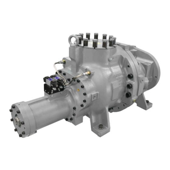
Rotary Screw Compressor
HPS 2709 and 2712
HPS 4009 and 4012
This manual contains installation, operation, and maintenance
instructions. Read thoroughly before beginning installation. Failure
to follow these instructions may result in personal injury or death,
damage to the unit, or incorrect operation.
Check www.FrickCold.com for the latest version of this publication.
Form 070.750-IOM2 (JUN 2022)
Installation – Operation – Maintenance
File:
Service Manual – Section 070
Replaces:
070.750-IOM2 (JAN 2021)
Dist:
3, 3a, 3b, 3c
Advertisement
Table of Contents
Troubleshooting

Related Manuals for Frick HPS 2709


Summary of Contents for Frick HPS 2709
- Page 1 070.750-IOM2 (JAN 2021) Dist: 3, 3a, 3b, 3c Rotary Screw Compressor HPS 2709 and 2712 HPS 4009 and 4012 This manual contains installation, operation, and maintenance instructions. Read thoroughly before beginning installation. Failure to follow these instructions may result in personal injury or death, damage to the unit, or incorrect operation.
-
Page 2: Table Of Contents
070.750-IOM2 (JUN 22) HPS 273 and 407 Rotary Screw Compressor Page 2 Installation - Operation - Maintenance Table of Contents General information Operation Introduction ..............3 Operation and start-up instructions ....... 17 Design limitations ............. 3 Ambient temperature effect on compressor operation .. 17 Job inspection .............. -
Page 3: General Information
Contact Johnson compressors. Controls-Frick Compressor Engineering for application Notice details. Frick screw compressor repair must only be done by Delivery inspection skilled mechanics who have completed training at Immediately after delivery examine all crates, boxes, and Frick screw compressor school. - Page 4 070.750-IOM2 (JUN 22) HPS 273 and 407 Rotary Screw Compressor Page 4 Installation - Operation - Maintenance Figure 1: Identification data plate Rotary screw compressor serial numbers identify the factory that the compressor was manufactured in and its build date. They are defined by the following information: Example: 1024 0 A 9 0000015 Z Plant Decade...
-
Page 5: Long-Term Storage
The standard Johnson Controls-Frick Warranty for an HPS 273 and 407 screw compressors covers 12 months from start-up or 18 months from shipment, whichever comes first. -
Page 6: Maintaining The Compressor In Storage
Never operate the compressor HPS 273 and 407 compressors in reverse rotation because this can result in damage. The Frick HPS 273 and 407 rotary screw compressors use mating asymmetrical profile helical rotors to provide • The suction and discharge flanges are ANSI B16.1 Class a continuous flow of vapor and are designed for high- 600 type for the HPS 273 and 407 compressor models. -
Page 7: Oil Pump, Optional
The Frick compressor includes a method of varying the internal Vi to match the system pressure ratio. Control of Balance piston oil requirements and regulation... -
Page 8: Construction Details
070.750-IOM2 (JUN 22) HPS 273 and 407 Rotary Screw Compressor Page 8 Installation - Operation - Maintenance Construction details Figure 5: HPS 273 and 407 viscosity requirement as function of speed Housing All HPS 273 and 407 screw compressors castings are 60-40-18 ductile iron to ensure structural integrity and me- chanical and thermal stability under all operating conditions. -
Page 9: Vibration And Sound Data
HPS 273 and 407 Rotary Screw Compressor 070.750-IOM2 (JUN 22) Installation - Operation - Maintenance Page 9 • In CO applications using miscible oil types POE and PAG, it is critical to keep water content to the lowest possible. Down to 10 ppm is the goal. The installation must have large filter dryers with replaceable elements that you can effectively service and vacuum dry before putting back into service. - Page 10 070.750-IOM2 (JUN 22) HPS 273 and 407 Rotary Screw Compressor Page 10 Installation - Operation - Maintenance This page is intentionally left blank.
-
Page 11: Installation
Outline dimensions Find complete dimensions and connection information on the outline drawing, which you can request by contacting Johnson Controls-Frick Sales. See Figure 11 and Figure 12. Holding charge and storage Every HPS 273 and 407 compressor is pressure and leak tested at the Johnson Controls–Frick factory and thor-... -
Page 12: Foundation
The weights of the kick bolts are not included with compressor. HPS 2709 and HPS 2712 assemblies respectively are 2,132 4. After setting the motor, check to see that the shafts kg (4,700 lb) and 2,241 kg (4,940 lb). The weights of the are correctly spaced for the coupling being used. -
Page 13: Coupling Alignment Requirements, For Foot-Mounted Motor Only
2.2 Vi to 5.0 Vi range. If you are unsure what Vi range the compressor has, pipe the main oil SB-2: Balance piston injection line to the SM-2 port. The HPS 2709 and SB-3: Shaft seal, outlet end bearings HPS 2712 both have factory-installed orifice plugs, SM-1 or SM-2: Main oil injection. -
Page 14: Compressor Oil
See Figure 11 and Figure 12. ing the use of filter elements other than Johnson Controls- Frick, or a warranty claim may be denied. Oil filter speci- Note: Total pressure drop is the difference between dis- fication b... -
Page 15: Dehydration/Evacuation Test
HPS 273 and 407 Rotary Screw Compressor 070.750-IOM2 (JUN 22) Installation Page 15 Compressor hydraulic system Warning Note: The solenoid valves and manifold block are available For high temperature applications, consult factory. as a sales order option. Some of the 3-way thermostatic valves do not work The compressor hydraulic system actuates the mov- at high temperatures and damage to thermostatic able slide valve (SV) to load and unload the compressor,... - Page 16 070.750-IOM2 (JUN 22) HPS 273 and 407 Rotary Screw Compressor Page 16 Installation Figure 9: Hydraulic schematic Callout Description Callout Description Direction control valve Compressor top view Screw in flow regulating needle valve Direction control valve...
-
Page 17: Operation
Before the start-up, complete the prestart check. See Operation and start-up instructions Prestart checklist in the Forms section. The Frick HPS 273 and 407 rotary screw compressors are Calibrating the linear transmitter components in an integrated system. Because of this, the... -
Page 18: Using An External Source Of Pressure
(SV is fully maintenance schedule. loaded). • Frick strongly suggests completing a baseline vibra- This provides the absolute capacity (CAPabs) range of the tion analysis for frequencies up to 7,000 Hz at normal compressor from minimum to maximum load. -
Page 19: Control System
HPS 273 and 407 Rotary Screw Compressor 070.750-IOM2 (JUN 22) Operation Page 19 4. After starting the compressor and it is operating, Frick suggests maintaining suction gas superheat at a mini- mum of 10°F. If operating at lower than 10°F suction superheat consult the factory. - Page 20 070.750-IOM2 (JUN 22) HPS 273 and 407 Rotary Screw Compressor Page 20 Operation This page is intentionally left blank.
-
Page 21: Maintenance General Information
HPS 273 and 407 Rotary Screw Compressor 070.750-IOM2 (JUN 22) Maintenance Page 21 Maintenance • Keep oil filters clean. If filters show increasing pressure drop, indicating dirt or water, stop the compressor and change filters. Running a compressor for long periods General information with high filter pressure drop may starve the compres- This section provides instructions for normal maintenance,... -
Page 22: Maintenance Schedule
6 in. Class 600 8 in. Class 600 Bolt size (in.) Torque* (ft-lb) Bolt size (in.) Torque (ft-lb) HPS 2709/2712 1 1/8 8 in. Class 600 12 in. Class 600 HPS 4009/4012 1 1/8 1 1/4 Note: Based on using stainless steel spiral wound gaskets and Grade 5 or stronger hex head bolts, lighlty oiled. -
Page 23: Maintenance Program
• Excessive liquid entering the compressor (slugging) the compressor unit: • Insufficient oil cooling • Only use Frick oil or high quality oils approved by John- • Excessive oil cooling son Controls-Frick for your application. • Incorrect gas line sizing •... -
Page 24: Troubleshooting The Hps 273 And 407 Compressors
1. Verify that main power to the unit is disconnected and tag the switch. Unless the service technician has been certified by Johnson Controls–Frick to rebuild our compressors, 2. Remove all tubing, piping, and wiring that is connects troubleshooting the compressor is limited to identi- to the compressor. -
Page 25: Forms
Compressor prestart checklist The installer must check and complete the following items before the arrival of the Frick Field Service Supervisor. You can find details on the checklist in this manual. Certain items on this checklist are reverified by the Frick Field Service Supervisor before the actual start-up. -
Page 26: Alignment Log For Electric Motor Driver
070.750-IOM2 (JUN 22) HPS 273 and 407 Rotary Screw Compressor Page 26 Forms Alignment log for electric motor driver Drive train alignment Ambient temperature at time of alignment ________ Oil separator temperature at time of alignment __________ Motor coupling type ____________ Size ___________ Distance between coupling hub faces ____________ Soft foot check OK as Found Shimming required... -
Page 27: Vibration Data Sheet
HPS 273 and 407 Rotary Screw Compressor 070.750-IOM2 (JUN 22) Forms Page 27 Vibration data sheet Date: _____________________________________ Sales order number: ____________________________ End user: __________________________________ Installing contractor: ___________________________ Address: _____________________________________ Service technician: _____________________________ Final hot alignment Equipment ID, as in Microlog: ________________ Compressor serial number: ______________________ Face... -
Page 28: Compressor Port Locations
Compressor port locations 070.750-IOM2 (JUN 22) HPS 273 and 407 Rotary Screw Compressor Page 28 Forms Figure 11: Compressor port locations, HPS 2709/2712 Table 10: 273 connection legend SC-6 Port Description Connection M30 x 3.5 lifting eye M30 x 3.5 lifting eye... - Page 29 HPS 273 and 407 Rotary Screw Compressor 070.750-IOM2 (JUN 22) Forms Page 29 Figure 12: Compressor port locations, HPS 4009/4012 Ø 558.8 (Ø 22.00) Table 11: 407 connection legend 1 1/4-7 UNC - 2B Compressor suction flange 2.19 in. threaded holes Port Description Connection...
- Page 30 070.750-IOM2 (JUN 22) HPS 273 and 407 Rotary Screw Compressor Page 30 Index Index ammonia heat pumps 14 heat pumps 14 radial runout 13 asymmetric profile 8 hot alignment 13 regulating valve 14 axial load 12 housing 8 rigging 11 axial runout 13 HPSH compressors 11 rotor housing...
- Page 31 HPS 273 and 407 Rotary Screw Compressor 070.750-IOM2 (JUN 22) Index Page 31 This page is intentionally left blank.
- Page 32 – Added Replacing the capacity linear transmitter: slide valve section Page 29 – Added Figure 12 January 2021 revisions Throughout – Removed HPSH nomenclature and changed to HPS – Updated Frick and JCI logos Page 3 – Updated Figure 1 Page 4 – Updated Figure 2 –...
Need help?
Do you have a question about the HPS 2709 and is the answer not in the manual?
Questions and answers