Table of Contents
Advertisement
Quick Links
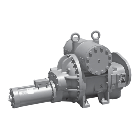
ROTARY SCREW COMPRESSORS
SGC 1913-2824, SGCB/H 3511-3519
Original SGXB 3519-3524, SGXH 3519 & 4013-4021
THIS MANUAL CONTAINS RIGGING, ASSEMBLY, START-UP,
AND MAINTENANCE INSTRUCTIONS. READ THOROUGHLY
BEFORE BEGINNING INSTALLATION. FAILURE TO FOLLOW THESE
INSTRUCTIONS MAY RESULT IN PERSONAL INJURY OR DEATH,
DAMAGE TO THE UNIT, OR IMPROPER OPERATION.
Please check www.johnsoncontrols.com/frick for the latest version of this publication.
Form 070.650-IOM (AUG 2015)
INSTALLATION - OPERATION - MAINTENANCE
File:
Replaces:
Dist:
SGC/SGX
MODELS:
SERVICE MANUAL - Section 070
070.650-IOM (NOV 2013)
3, 3a, 3b, 3c
Advertisement
Table of Contents

Related Manuals for Frick SGC 1913


Summary of Contents for Frick SGC 1913
- Page 1 THIS MANUAL CONTAINS RIGGING, ASSEMBLY, START-UP, AND MAINTENANCE INSTRUCTIONS. READ THOROUGHLY BEFORE BEGINNING INSTALLATION. FAILURE TO FOLLOW THESE INSTRUCTIONS MAY RESULT IN PERSONAL INJURY OR DEATH, DAMAGE TO THE UNIT, OR IMPROPER OPERATION. Please check www.johnsoncontrols.com/frick for the latest version of this publication.
-
Page 2: Table Of Contents
070.650-IOM (AUG 2015) SGC ROTARY SCREW COMPRESSOR Page 2 INSTALLATION - OPERATION - MAINTENANCE Contents GENERAL INFORMATION OPERATION PREFACE ................3 OPERATION AND START-UP INSTRUCTIONS ....23 DESIGN LIMITATIONS ............3 LOW AMBIENT TEMPERATURE OPERATION ....23 JOB INSPECTION .............. 3 INITIAL START-UP ............23 STANDARD BARE COMPRESSOR ........ -
Page 3: General Information
Johnson Controls-Frick Sales Administration Department, MAINTENANCE procedures as recommended by Johnson in Waynesboro, PA. Controls-Frick for SGC, SGCB/H and SGXB/H Rotary Screw COMPRESSOR IDENTIFICATION Compressors (referred to in this document as SGC or SGX). The term SGC refers to the 1913, 1918, 2313, 2317, 2321,... -
Page 4: Long Term Storage
95mm* 2 Gal. 233mm 15 Gal. The standard Johnson Controls-Frick Warranty for an SGC/ 120mm* 3 Gal. 283mm 25 Gal. SGX screw compressor covers twelve (12) months from 163mm* 8 Gal. -
Page 5: Description
11. Shaft rotation clockwise facing compressor, suitable for DESCRIPTION all types of drives. SEE FOLLOWING WARNING. SGC/SGX COMPRESSORS WARNING Frick SGC/SGX rotary screw compressors utilize mating asymmetrical profile helical rotors to provide a continuous Compressor rotation is clockwise when facing the flow of vapor and they are designed for both high-pressure compressor drive shaft. The compressor should never low-pressure applications. -
Page 6: Oil Pump
VOLUMIZER VARIABLE VOLUME RATIO CONTROL: The All SGX compressors are equipped with Squeeze Film Frick compressor includes a method of varying the internal Dampers (SFD) in the rotor blocking diameters. Depending volume ratio to match the system pressure ratio. Control of... -
Page 7: Installation
SGCH 3511 & SGCB 3511 DWG# 534E0966 ceeded (See CoolWare). Refer to Johnson Controls - Frick SGCH 3515 & SGCB 3515 DWG# 534E0971 Compressor Control Panel instruction 090.020-M for addi- SGCH 3519 &... - Page 8 4" CLASS 300 FLANGE SC-7: SEAL WEEPAGE TE-1: SUCTION GAS TEMP. ELEMENT T: MANIFOLD BLOCK TANK SE-2: SLIDE VALVE LINEAR TRANSMITTER SE-1: SLIDE STOP SM-1: MAIN OIL LINEAR TRANSMITTER SC-8: CLOSED THREAD DRAIN INJECTION Figure 3. Port Locations, SGC 1913/1918...
- Page 9 SGC ROTARY SCREW COMPRESSOR 070.650-IOM (AUG 2015) INSTALLATION Page 9 PORT THREAD SIZE NOTE SB-3 1Z\zn - 12 UN-2B SC-5 ⁹\zn - 18 UNF-2B SC-6 ⁹\zn - 18 UNF-2B SC-7 Z\₈ - 27 NPTF SC-8 1Z\zn - 12 UN-2B SC-9 ⁹\zn - 18 UNF-2B SC-11 1B\zn-12 UN-2B...
- Page 10 070.650-IOM (AUG 2015) SGC ROTARY SCREW COMPRESSOR Page 10 INSTALLATION PORT THREAD SIZE NOTE SB-3 1 Z\₄ Square Flange SC-5 ⁹\zn - 18 UNF-2B SC-6 ⁹\zn - 18 UNF-2B SC-7 Z\₈ - 27 NPTF SC-8 1B\zn - 12 UN-2B SC-9 ⁹\zn - 18 UNF-2B SC-13 ⁹\zn - 18 UNF-2B...
- Page 11 SGC ROTARY SCREW COMPRESSOR 070.650-IOM (AUG 2015) INSTALLATION Page 11 PORT THREAD SIZE NOTE SB-3 1 Z\₄ Square Flange SC-5 ⁹\zn - 18 UNF-2B SC-6 ⁹\zn - 18 UNF-2B SC-7 Z\₈ - 27 NPTF SC-8 1B\zn - 12 UN-2B SC-9 ⁹\zn - 18 UNF-2B SC-13 ⁹\zn - 18 UNF-2B...
- Page 12 070.650-IOM (AUG 2015) SGC ROTARY SCREW COMPRESSOR Page 12 INSTALLATION SC-7: SEAL WEEPAGE PORT THREAD SIZE NOTE SB-2 ³\₄ - 14 NPTF SB-3 1Z\₂ 11Z\₂ NPTF SC-3 Z\₂ - 14 NPTF SC-4 Z\₂ - 14 NPTF SC-5 ³\₈ - 18 NPTF SC-6 ³\₈...
- Page 13 SGC ROTARY SCREW COMPRESSOR 070.650-IOM (AUG 2015) INSTALLATION Page 13 SC-7: SEAL PORT THREAD SIZE NOTE WEEPAGE SB-2 ³\₄ - 14 NPTF SB-3 1Z\₂ - 11Z\₂ NPTF SB-4 1 - 11Z\₂ NPTF SC-3 Z\₂ - 14 NPTF SC-4 Z\₂ - 14 NPTF SC-5 ³\₈...
- Page 14 070.650-IOM (AUG 2015) SGC ROTARY SCREW COMPRESSOR Page 14 INSTALLATION X - Mandatory ST-1: SUCTION TEMPERATURE SD-1: COALESCER BLEED/SUCTION PRESSURE connection SC-5: SUCTION PRESSURE SM-1: MAIN OIL INJECTION O - Optional connection SC-9: CLOSED THREAD SV-1: VAPOR INJECTION S - Service PRESSURE connection SC-9: CLOSED THREAD PRESSURE...
-
Page 15: Holding Charge And Storage
Page 15 HOLDING CHARGE AND STORAGE SGC/SGX compressors are pressure and leak tested at the Johnson Controls–Frick factory and then thoroughly evacu- ated and charged with dry nitrogen to ensure integrity dur- ing shipping and short term storage prior to installation. -
Page 16: Customer Connections
Advanced control systems like the Frick Quantum HD will Other connections are available for instrumentation, oil monitor the oil pressure in many more ways in order to return, and service as noted on the Dimensional Outline keep the compressor running beyond these basic limits. - Page 17 SGC ROTARY SCREW COMPRESSOR 070.650-IOM (AUG 2015) INSTALLATION Page 17 Balance Shaft Seal Piston Capacity Increase Increase Decrease Capacity Decrease Linear Transmitter Slide Stop Slide Valve For Capacity Indication (Internal Oil Feed: 193 - 283 models) Figure 14. Balance Piston Location & Capacity/Vi Manifold Designations (193 - 283) SB-2 Balance Inlet End...
-
Page 18: Oil Cooling Requirements
Frick Coolware can calculate oil flows, pressure and changes should be expected. In that case, contact engi- temperature required. All nominal operation conditions, neering. Use the Compressor Operating Log Sheet to fill in including SB-3 and SB-4 oil pressure requirements, should your nominal operating conditions. -
Page 19: Oil Filter(S)
If you are using the Johnson Controls – Frick motor mount, the mount is machined to ensure that motor to compressor... -
Page 20: Coupling Alignment Requirements (Foot Mounted Only)
MOUNTING” section for mounting details). operation. Connect to +/- and signal as shown in the wiring diagram in Figure 19. Refer to Frick compressor panel If you are using a foot mounted motor, it is essential that instructions 090.040-O for calibration procedure. -
Page 21: Directional Control Valves
Compressor Loading (Single-acting): The compressor in the OPERATION chapter. For control system information loads when SV solenoid YY2 is energized and oil flows from refer to Frick Compressor Control Panel 090.040-O. See the unload side of the cylinder out port SC1, through valve wiring diagram in Figure 22. ports A and T to compressor suction. Simultaneously, discharge pressure loads the slide valve. -
Page 22: Volumizer Volume Ratio Control
070.650-IOM (AUG 2015) SGC ROTARY SCREW COMPRESSOR Page 22 OPERATION VOLUMIZER VOLUME RATIO CONTROL NOTICE Open valve at SC3 To control the rate of loading and unloading, throttle Open valve at SC4 the needle valve at SC1 port. Compressor Vi increase: The volume ratio Vi is increased DOUBLE-ACTING MODE - (Low Differential Application) when MSS solenoid valve YY3 is energized and oil flows from the oil manifold through valve ports P and A to... -
Page 23: Operation And Start-Up Instructions
Page 23 Operation OPERATION AND START-UP INSTRUCTIONS INITIAL START-UP Frick SGC/SGX Rotary Screw Compressors will be Prior to the start-up, the prestart check must be components in an integrated system. As such the compressor accomplished. See Forms section for Checklist. -
Page 24: Maintenance
070.650-IOM (AUG 2015) SGC ROTARY SCREW COMPRESSOR Page 24 MAINTENANCE Maintenance GENERAL INFORMATION 5. Protect the compressor during long periods of This section provides instructions for normal maintenance, shutdown. If the compressor will be sitting for long periods a recommended maintenance program, and troubleshooting without running, it is advisable to evacuate to low pressure and correction guides. -
Page 25: Maintenance Schedule
SGC ROTARY SCREW COMPRESSOR 070.650-IOM (AUG 2015) MAINTENANCE Page 25 MAINTENANCE SCHEDULE Recommended schedule for SGC/SGX Frick rotary screw compressor preventive maintenance operations. FREQUENCY OR HOURS OF OPERATION (MAXIMUM) MAINTENANCE Change Oil As Directed By Oil Analysis Oil Analysis Every 6 Months... -
Page 26: Vibration Analysis
3. Excessively high discharge pressure. compressor unit: 4. Excessively high or low temperature coolant to the oil 1. Only use Frick oil or high quality oils approved by Johnson cooler. Controls - Frick for your application. 5. Excessive liquid entering the compressor (slugging). - Page 27 • Piston Seals worn out/damaged. Contact Johnson Controls - Frick Service for assistance. NOTICE Unless the Service Technician has been certified by Johnson Controls – Frick to rebuild our compressors, troubleshooting the compressor is limited to identifying the probable cause. If a mechanical problem is suspected contact Johnson Controls –...
-
Page 28: Capacity Linear Transmitter Replacement - Slide Valve
070.650-IOM (AUG 2015) SGC ROTARY SCREW COMPRESSOR Page 28 MAINTENANCE TROUBLESHOOTING GUIDE The linear transmitter, with hermetic enclosure is based on (cont.) the inductive measuring principle. It features removable CAPACITY LINEAR TRANSMITTER REPLACEMENT - electronics (from the sensor well) eliminating the need to SLIDE VALVE evacuate the compressor for replacement. -
Page 29: Forms
SGC ROTARY SCREW COMPRESSOR 070.650-IOM (AUG 2015) MAINTENANCE Page 29 FORMS ROTARY SCREW COMPRESSOR OPERATING LOG SHEET... - Page 30 READ THIS FIRST: COMPRESSOR PRESTART CHECKLIST The following items MUST be checked and completed by the installer prior to the arrival of the Frick Field Service Supervisor. Details on the checklist can be found in this manual. Certain items on this checklist will be reverified by the Frick Field Service Supervisor prior to the actual start-up.
- Page 31 SGC ROTARY SCREW COMPRESSOR 070.650-IOM (AUG 2015) MAINTENANCE Page 31 DRIVE TRAIN ALIGNMENT Ambient Temperature at Time of Alignment _______ Oil Separator Temperature at Time of Alignment ________ Motor Coupling Type ___________ Size ___________ Distance Between Coupling Hub Faces __________ Soft Foot Check OK as Found Shimming Required...
-
Page 32: Vibration Data Sheet
070.650-IOM (AUG 2015) SGC ROTARY SCREW COMPRESSOR Page 32 MAINTENANCE VIBRATION DATA SHEET Date: __________________________________________ Sales Order Number: ________________________________ End User: _______________________________________ Installing Contractor: ________________________________ Address: __________________________________________ Service Technician: __________________________________ Equipment ID (As in Microlog): ____________________ Compressor Serial Number: __________________________ Unit Serial Number: _________________________________ National Board Number: _____________________________ Running Hours: _____________________________________... - Page 33 SGC ROTARY SCREW COMPRESSOR 070.650-IOM (AUG 2015) INSTALLATION - OPERATION - MAINTENANCE Page 33 Notes...
- Page 34 070.650-IOM (AUG 2015) SGC ROTARY SCREW COMPRESSOR Page 34 INSTALLATION - OPERATION - MAINTENANCE Index accumulator, 3 gaskets, 28 Oil analysis, 24 Allowable Flange Loads, 16 gas load, 26 oil cooler, 26 angular-contact bearings, 5 oil cooling system, 23 Antifriction bearings, 6 oil filter cartridges, 24 hermetic enclosure, 28 ASHRAE, 3...
- Page 35 SGC ROTARY SCREW COMPRESSOR 070.650-IOM (AUG 2015) INSTALLATION - OPERATION - MAINTENANCE Page 35 Start-up, 30 storage, 15 suction accumulator, 24 suction gas, 5 suction line, 3 suction pressure, 26 suction strainer, 23, 24 suction strainers, 5 superheating, 5 system piping, 26 thermal stability, 6 transmitter unit, 28 traps, 3...
- Page 36 JOHNSON CONTROLS Supersedes: 070.650-IOM (2013-11) 100 Cumberland Valley Avenue Subject to change without notice Waynesboro, PA 17268-1206 USA Published in USA • 09/18 • PDF Phone: 717-762-2121 • FAX: 717-762-8624 www.johnsoncontrols.com/frick © 2018 Johnson Controls Int'l PLC - ALL RIGHTS RESERVED...
Need help?
Do you have a question about the SGC 1913 and is the answer not in the manual?
Questions and answers