Table of Contents
Advertisement
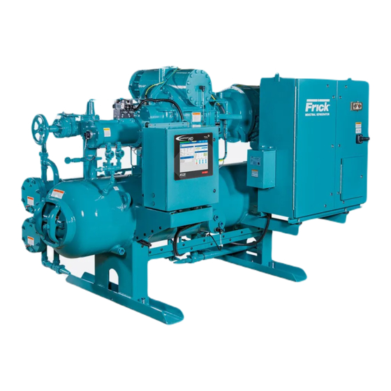
Installation - Operation - Maintenance
ROTARY SCREW COMPRESSOR UNITS
ALL REFRIGERANTS
100 through 480
THIS MANUAL CONTAINS RIGGING, ASSEMBLY, START-UP, AND
MAINTENANCE INSTRUCTIONS. READ THOROUGHLY BEFORE
BEGINNING INSTALLATION. FAILURE TO FOLLOW THESE IN-
STRUCTIONS COULD RESULT IN DAMAGE OR IMPROPER OPERA-
TION OF THE UNIT.
RWF
MODELS
S70-600 IOM/MAY 2001
File:
SERVICE MANUAL - Section 70
Replaces:
S70-600 IOM/MAR 2000
Dist:
3, 3a, 3b, 3c
Advertisement
Table of Contents
Troubleshooting

Subscribe to Our Youtube Channel
Related Manuals for Frick RWF Series


Summary of Contents for Frick RWF Series
- Page 1 S70-600 IOM/MAY 2001 File: SERVICE MANUAL - Section 70 Replaces: S70-600 IOM/MAR 2000 Dist: 3, 3a, 3b, 3c Installation - Operation - Maintenance ROTARY SCREW COMPRESSOR UNITS ALL REFRIGERANTS MODELS 100 through 480 THIS MANUAL CONTAINS RIGGING, ASSEMBLY, START-UP, AND MAINTENANCE INSTRUCTIONS.
-
Page 2: Table Of Contents
S70-600 IOM RWF ROTARY SCREW COMPRESSOR UNITS Page 2 INSTALLATION - OPERATION - MAINTENANCE Contents PREFACE ................. 3 COMPRESSOR SHUTDOWN and START-UP ....18 DESIGN LIMITATIONS ............3 GENERAL INSTRUCTIONS FOR REPLACING JOB INSPECTION ............3 COMPRESSOR UNIT COMPONENTS ....19 TRANSIT DAMAGE CLAIMS .......... -
Page 3: Preface
The unit RWF Rotary Screw Compressor Units. data plate containing unit model, serial number and Frick sales order number is mounted on the side of the compres- For information about the functions of the Quantum control sor base. -
Page 4: Foundation
1200 a mass is required to effectively dampen these relatively high frequency vibrations. Frick recommends consulting a licensed architect to deter- Firmly anchoring the compressor package to a suitable foun- mine the proper foundation requirements for any large en- dation by proper application of grout and elimination of pip- gine or turbine drive. -
Page 5: Checking Motor/Compressor Rotation
HOLDING CHARGE AND STORAGE Each RWF compressor unit is pressure and leak tested at COMPRESSOR/MOTOR COUPLING the Frick factory and then thoroughly evacuated and charged INSTALLATION with dry nitrogen to ensure the integrity of the unit during shipping and short term storage prior to installation. -
Page 6: Oil Charge
Should additional heating capacity be required because of low ambient temperature, contact Current thermosyphon systems are using two-pass oil cool- Frick. The heaters are energized only when the unit is not in ers and flow rates based on 3:1 overfeed. operation. -
Page 7: Liquid Injection Oil Cooling (Optional)
RWF ROTARY SCREW COMPRESSOR UNITS S70-600 IOM INSTALLATION Page 7 INSTALLATION - The plate and shell type thermosyphon 2. The liquid level in the refrigerant source must be 6 to 8 oil cooler with oil-side piping and a thermostatically con- feet minimum above the center of the oil cooler. -
Page 8: Liquid Line Sizes/Receiver Volume
The water supply must be sufficient to meet the required flow. Frick recommends a closed-loop system for the waterside of the oil cooler. Careful attention to water treatment is es- sential to ensure adequate life of the cooler if cooling tower water is used. -
Page 9: Economizer - High Stage (Optional)
RWF ROTARY SCREW COMPRESSOR UNITS S70-600 IOM INSTALLATION Page 9 The recommended economizer systems are shown below. ECONOMIZER - HIGH STAGE (OPTIONAL) Notice that in all systems there should be a strainer (STR) and a check valve (VCK) between the economizer vessel The economizer option provides an increase in system ca- and the economizer port on the compressor. -
Page 10: Electrical
Page 10 INSTALLATION noid on the PRR unit and the liquid feed solenoid on the DX chased separately from Frick . Starter packages should con- vessel off of a common signal to avoid liquid overfeed on sist of: the DX economizer system. -
Page 11: Current Transformer (Ct) Ratios
120/240 V. IN, 120 V. OUT 200:5 100:5 100:5 50:5 50:5 SOLA #63-23-112-4, 120 VA, 60 HZ 200:5 200:5 100:5 100:5 50:5 SHOWN HERE- CONSULT FRICK FOR OTHER VOLTAGES/HZ 200:5 200:5 100:5 100:5 100:5 300:5 200:5 200:5 100:5 100:5 Figure 11 - Recommended Regulator Installation... -
Page 12: Operation And Start-Up Instructions
OPERATION and START-UP INSTRUCTIONS when facing the compressor drive shaft. (See Figure 12) The compres- The Frick RWF Rotary Screw Compressor Unit is an inte- sor should never be operated in reverse rotation as bear- grated system consisting of seven major subsystems: ing damage will result. -
Page 13: Cold-Start System
DO NOT ATTEMPT TO SERVICE THE COMPRESSOR OIL SEPARATION SYSTEM COLD START VALVE. PLEASE CON- TACT THE FRICK SERVICE The RWF is an oil flooded screw compressor. Most of the oil DEPARTMENT. discharged by the compressor separates from the gas flow in the oil charge reservoir. -
Page 14: Compressor Hydraulic System
S70-600 IOM RWF ROTARY SCREW COMPRESSOR UNITS Page 14 OPERATION COMPRESSOR HYDRAULIC SYSTEM SEE HYDRAULIC SCHEMATIC The compressor hydraulic system moves the movable slide FOR FUNCTIONAL valve (MSV) to load and unload the compressor. It also VIEW OF VALVE moves the movable slide stop (MSS) to increase or de- OPERATION crease the compressor’s volume ratio (Vi). -
Page 15: Compressor Oil Cooling Systems
(PDCV) to prevent migration of high pres- sure gas during shutdown. A Frick-installed timer limits the 4. Monitor the oil temperature of the compressor. If the oil high pressure gas to only thirty seconds duration, since in- temperature rises above 170 °... -
Page 16: Suction Check Valve Bypass
S70-600 IOM RWF ROTARY SCREW COMPRESSOR UNITS Page 16 OPERATION SUCTION CHECK VALVE BYPASS LOW AMBIENT OPERATION The RWF unit is equipped with a low-pressure-drop suc- It is recommended that oil separators be insulated as a tion check valve bolted directly to the compressor housing. minimum requirement to preserve the heat generated by Units that have an 8"... -
Page 17: Initial Start-Up
Initial start-up must be performed under the supervision run at the proper speed and discharge pressure. Exceed- of a FRICK authorized start-up representative to pre- ing design conditions creates a potential hazard. vent voiding the compressor warranty. Prior to the 3. -
Page 18: General Information
S70-600 IOM RWF ROTARY SCREW COMPRESSOR UNITS Page 18 MAINTENANCE GENERAL INFORMATION This section provides instructions for normal maintenance, a recommended maintenance program, troubleshooting and 1. IF UNIT IS RUNNING, PRESS [STOP] KEY. correction guides, and typical P and I diagrams. For typical 2. -
Page 19: General Instructions For Replacing Compressor Unit Components
6. Isolate the low pressure transducer, PE-4, to prevent Use of oils other than Frick Oil in damage during pressurization and leak test. Frick compressors must be ap- proved in writing by Frick engineer- 7. -
Page 20: Strainer - Liquid Injection
5. Install new coalescer filter element(s). the oil-charging valve located on top of the separator. Using a pressure-type oil pump and recommended Frick oil, open Seat element in center of locating the charging valve and fill the separator until the oil level is tabs on separator bulkhead. -
Page 21: Demand Pump Disassembly
RWF ROTARY SCREW COMPRESSOR UNITS S70-600 IOM MAINTENANCE Page 21 oil will fill up in the separator faster than it shows in the the locknut counterclockwise and remove locknut. See Fig- sight glass. Refer to the table in the OIL CHARGE section ure 18 or 19. -
Page 22: Demand Pump Assembly
S70-600 IOM RWF ROTARY SCREW COMPRESSOR UNITS Page 22 MAINTENANCE Clean all parts thoroughly and examine for wear or dam- 3. Start seal seat in seal housing bore. If force is neces- age. Check lip seals, ball bearings, bushing, and idler pin sary, protect seal face with a clean cardboard disc and gen- and replace if necessary. -
Page 23: Troubleshooting The Demand Pump
RWF ROTARY SCREW COMPRESSOR UNITS S70-600 IOM MAINTENANCE Page 23 13. Pack lubrication chamber between inner ball bearing INSTALLATION OF CARBON GRAPHITE and double-row ball bearing in the thrust-bearing assem- BUSHINGS bly approximately one-half full of multipurpose grease, NLGI #2. The thrust-bearing assembly will take the remaining When installing carbon graphite bushings, extreme care space. -
Page 24: Preventative Maintenance
S70-600 IOM RWF ROTARY SCREW COMPRESSOR UNITS Page 24 MAINTENANCE Pressure Gauge - Discharge Port e. Relief valve set too low or stuck open. f. Pump worn out. 1. High reading would indicate: g. Tighten end clearance. a. High viscosity and small and/or long discharge line. h. -
Page 25: Recommended Maintenance Program
1. Only use Frick refrigeration oil or high quality refrigera- tion oils approved by Frick for your application. 2. Use vibration readings taken from the new unit at start-up as the base line reference. -
Page 26: Operating Log
S70-600 IOM RWF ROTARY SCREW COMPRESSOR UNITS Page 26 MAINTENANCE OPERATING LOG The use of an operating log as included in this manual (see Table of Contents) permits thorough analysis of the operation of a refrigeration system by those responsible for its maintenance and servicing. Continual recording of gauge pressures, tempera- tures, and other pertinent information, enables the observer and serviceman to be constantly familiar with the operation of the system and to recognize immediately any deviations from normal operating conditions. -
Page 27: Troubleshooting Guide
COLD START VALVE. PLEASE CON- rary. When system conditions return to normal the units’ liq- TACT THE FRICK SERVICE DE- uid injection will overfeed and oil temperature will drop. In PARTMENT. solving the wrong problem a new problem was created. -
Page 28: Pressure Transducers - Replacement
S70-600 IOM RWF ROTARY SCREW COMPRESSOR UNITS Page 28 MAINTENANCE 6. Measure the voltage of PE-1 on connector P4 (termi- PRESSURE TRANSDUCER CONVERSION DATA nals WHT and BLK) on the SBC. 200 psi 500 psi Sensor Range - PSI Range - PSIG* 7. -
Page 29: Position Potentiometer Replacement And Adjustment
RWF ROTARY SCREW COMPRESSOR UNITS S70-600 IOM MAINTENANCE Page 29 SV POSITION POTENTIOMETER REPLACEMENT AND ADJUSTMENT FLEXIBLE COUPLING The Slide Valve Position potentiometer is located on the end of the compressor unloader cylinder (applies to mod- POTENTIOMETER els 100 - 270), see Figure 23. 1. -
Page 30: Volumizer Transmitter Replacement - Slide Stop
S70-600 IOM RWF ROTARY SCREW COMPRESSOR UNITS Page 30 MAINTENANCE VOLUMIZER ® TRANSMITTER OIL LEVEL TRANSMITTER REPLACEMENT - SLIDE STOP REPLACEMENT ® The VOLUMIZER Transmitter is located on the right side of The Oil Level Transmitter is located on the front of the sepa- the compressor (facing shaft) at the inlet end (see Figure 25). -
Page 31: Troubleshooting The Rwf Compressor
Unloader piston stuck. Contact Frick Factor or Frick service for assistance. Slipper seals worn out or damaged. Contact Frick Factor or Frick service for assistance. NOTE: Troubleshooting the compressor is limited to identifying the probable cause. If a mechanical problem is suspected contact the Service Department, Frick . -
Page 32: Hydraulic System
EITHER DIRECTION Solenoid service valves may be closed. Open. Manually actuate solenoid. If slide stop will not move mechanical problems are indicated. Consult Frick factor or Frick service. TROUBLESHOOTING THE LIQUID INJECTION OIL COOLING SYSTEM SYMPTOM PROBABLE CAUSES and CORRECTIONS HIGH OIL TEMPERATURE Insufficient liquid supply. -
Page 33: Demand Pump System
RWF ROTARY SCREW COMPRESSOR UNITS S70-600 IOM MAINTENANCE Page 33 TROUBLESHOOTING THE DEMAND PUMP SYSTEM SYMPTOM PROBABLE CAUSES and CORRECTIONS PUMP WILL NOT PRODUCE Check pump rotation. ENOUGH OIL PRESSURE TO START COMPRESSOR Check that service valves are open. Filter cartridges may be blocked. Check PSID across filters. Strainer may be blocked. -
Page 34: Thermal Expansion Valves
S70-600 IOM RWF ROTARY SCREW COMPRESSOR UNITS Page 34 MAINTENANCE THERMAL EXPANSION VALVES In situations where system load conditions increase or de- crease over extended periods of time and the liquid injec- tion thermal expansion valve is not adequate for the new conditions, an improvement in valve performance may be achieved by increasing or decreasing discharge tube size. -
Page 35: Jordan Temperature Regulator Valve
RWF ROTARY SCREW COMPRESSOR UNITS S70-600 IOM MAINTENANCE Page 35 If the hole in the valve plate is to the left and the slot in the JORDAN valve disc is on the top this valve is set for Direct Acting (see TEMPERATURE REGULATOR VALVE figure 34). -
Page 36: Motor Replacement
130°F for ammonia and 140°F 11. Reattach the drive coupling. for R-22. Check with Frick service for recommended oil tem- peratures for other refrigerants. 12. The shaft alignment must be checked and tolerances verified with the Frick service dept. -
Page 37: P & I Diagrams
RWF ROTARY SCREW COMPRESSOR UNITS S70-600 IOM MAINTENANCE Page 37 P & I DIAGRAM... - Page 38 S70-600 IOM RWF ROTARY SCREW COMPRESSOR UNITS Page 38 MAINTENANCE P & I DIAGRAM - OPTIONAL DUAL OIL FILTERS, DEMAND OIL PUMP, THERMAL CONTROL VALVE SEPARATOR TO COMPRESSOR PALL TAHH OPTIONAL CV-2 DEMAND STR-2 OIL PUMP PM-1 CV-1 PDAH OF-1 OPTIONAL THERMAL REFRIGERANT...
- Page 39 RWF ROTARY SCREW COMPRESSOR UNITS S70-600 IOM MAINTENANCE Page 39 P & I DIAGRAM, LIQUID INJECTION – SINGLE PORT P & I DIAGRAM, LIQUID INJECTION – DUAL PORT...
- Page 40 S70-600 IOM RWF ROTARY SCREW COMPRESSOR UNITS Page 40 MAINTENANCE P & I DIAGRAM, LIQUID INJECTION – BOOSTER...
-
Page 41: Wiring Harness
RWF ROTARY SCREW COMPRESSOR UNITS S70-600 IOM MAINTENANCE Page 41 WIRING HARNESS - External Transducers for Board #1... - Page 42 S70-600 IOM RWF ROTARY SCREW COMPRESSOR UNITS Page 42 MAINTENANCE WIRING HARNESS - External AC to Heaters and Valves...
- Page 43 RWF ROTARY SCREW COMPRESSOR UNITS S70-600 IOM MAINTENANCE Page 43 WIRING HARNESS - Internal Analog Board #1 CAV NO. WIRE NO. 1.1.1 1.1.2 1.1.4 1.1.5 1.2.1 1.2.2 1.2.4 1.2.5 1.3.4 1.3.5 1.3.6 1.4.1 1.4.2 1.4.3 1.4.4 1.4.5 1.4.6 1.5.1 1.5.2 1.5.3 1.7.4 1.7.5...
-
Page 44: Proper Installation Of Electronic Equipment In An Industrial Environment
S70-600 IOM RWF ROTARY SCREW COMPRESSOR UNITS Page 44 PROPER INSTALLATION OF ELECTRONIC EQUIPMENT PROPER INSTALLATION OF ELECTRONIC EQUIPMENT IN AN INDUSTRIAL ENVIRONMENT to provide a “clean” separate source voltage in order to In today’s refrigeration plants, electronic controls have found prevent EMI, from other equipment in the plant, from inter- their way into almost every aspect of refrigeration control. - Page 45 RWF ROTARY SCREW COMPRESSOR UNITS S70-600 IOM PROPER INSTALLATION OF ELECTRONIC EQUIPMENT Page 45 Never run any wires through an electronic control panel GROUNDING that do not relate to the function of the panel. Electronic control panels should never be used as a junction box. Grounding is the most important factor for successful op- These wires may be carrying large transients that will inter- eration and is also the most overlooked.
- Page 46 S70-600 IOM RWF ROTARY SCREW COMPRESSOR UNITS Page 46 PROPER INSTALLATION OF ELECTRONIC EQUIPMENT Never add relays, starters, timers, transformers, etc. in- PLANT SUPPLY side an electronic control panel without first contacting TRANSFORMER the manufacturer. Contact arcing and EMI emitted from 3-PHASE these devices can interfere with the electronics.
-
Page 47: Forms
RWF ROTARY SCREW COMPRESSOR UNITS S70-600 IOM MAINTENANCE Page 47 OPERATING LOG SHEET... - Page 48 The following items MUST be checked and completed by the installer prior to the arrival of the Frick Field Service Supervisor. Details on the checklist can be found in this manual. Certain items on this checklist will be reverified by the Frick Field Service Supervisor prior to the actual start-up. Mechanical Checks...
- Page 49 H.P. _________ RPM ________ Serial # ________________________ Service Factor ______ Voltage ______ Hz __________ FLA ________ Design ______ Code ____ Starter Size ____ Special Options DX Economizer Frick Supplied Starter PC Control System Other Prestart Checks Position of all valves...
- Page 50 S70-600 IOM RWF ROTARY SCREW COMPRESSOR UNITS Page 50 MAINTENANCE Adjustable Safety Setpoints High Discharge Pressure Stop Load _____ Force Unload ____ Alarm ______ Delay _____ Shutdown ____ Delay ____ High Discharge Temp. Stop Load _____ Force Unload ____ Alarm ______ Delay _____ Shutdown ____ Delay ____ Motor Amps ____ Volts _____ Service Factor _______ Horsepower _______ CT Factor ______ Recycle Delay ______...
- Page 51 RWF ROTARY SCREW COMPRESSOR UNITS S70-600 IOM MAINTENANCE Page 51 VIBRATION DATA SHEET Date: _________________________________________ Sales Order Number: ____________________________ End User: _____________________________________ Installing Contractor: ____________________________ Address: ______________________________________ Service Technician: ______________________________ Final Hot Alignment Equipment ID (As in Microlog): _____________________ Compressor Serial Number: ______________________ Unit Serial Number: _____________________________ National Board Number: _________________________ Running Hours: ________________________________...
-
Page 52: Recommended Spare Parts
S70-600 IOM RWF ROTARY SCREW COMPRESSOR UNITS Page 52 MAINTENANCE RECOMMENDED SPARE PARTS - CURRENT DESIGN QUANTUM™ CONTROL: Assembly, VGA Display, Phillips (Display only, 649C1078H01) 642C0052G01 Inverter, Sharp & Phillips (TDK) 333Q0001582 Power Supply 640C0022G01 Cable, CCFT Backlight Inverter (for Phillips Display) 649D4824H01 Keypad, Overlay 640D0060H01... - Page 53 RWF ROTARY SCREW COMPRESSOR UNITS S70-600 IOM MAINTENANCE Page 53...
- Page 54 S70-600 IOM RWF ROTARY SCREW COMPRESSOR UNITS Page 54 MAINTENANCE...
- Page 55 RWF ROTARY SCREW COMPRESSOR UNITS S70-600 IOM MAINTENANCE Page 55...
- Page 56 YORK Refrigeration Systems 100 CV Avenue • P.O. Box 997 • Waynesboro, Pennsylvania USA 17268-0997 Phone: 717-762-2121 • FAX: 717-762-8624 • www.frickcold.com © 2003 YORK Refrigeration Systems...
Need help?
Do you have a question about the RWF Series and is the answer not in the manual?
Questions and answers