Table of Contents
Advertisement
Quick Links
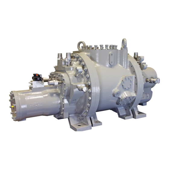
Rotary Screw Compressor
SBTP 355 and 408 Series
This manual contains installation, operation, and maintenance
instructions. Read thoroughly before beginning installation. Failure
to follow these instructions may result in personal injury or death,
damage to the unit, or incorrect operation.
Check www.FrickCold.com for the latest version of this publication.
Form 070.655-IOM (FEB 2022)
Installation – Operation – Maintenance
File:
Service Manual – Section 070
Replaces:
070.655-IOM (MAY 2019)
Distribution: 3, 3a, 3b, 3c
Advertisement
Table of Contents
Troubleshooting

Subscribe to Our Youtube Channel
Related Manuals for Frick SBTP 355 Series


Summary of Contents for Frick SBTP 355 Series
- Page 1 Form 070.655-IOM (FEB 2022) Installation – Operation – Maintenance File: Service Manual – Section 070 Replaces: 070.655-IOM (MAY 2019) Distribution: 3, 3a, 3b, 3c Rotary Screw Compressor SBTP 355 and 408 Series This manual contains installation, operation, and maintenance instructions. Read thoroughly before beginning installation. Failure to follow these instructions may result in personal injury or death, damage to the unit, or incorrect operation.
-
Page 2: Table Of Contents
Low ambient operation ..........20 Compressor identification ..........3 Initial start-up ..............20 Description ................ 4 Initial start-up procedure .......... 20 Frick SBTP compressor ..........4 Normal start-up procedure ........20 Compressor lubrication system ........4 Maintenance Oil pump ............... 5 Construction details............ -
Page 3: General Information
A screw compressor is a vapor pump. To ensure that ordering repair parts, provide the model, serial, and working fluid in the liquid state is not being ingested, per- Frick sales order numbers from the data plate. See form the following checks: Figure 1. -
Page 4: Description
The shaft rotation clockwise facing compressor from Frick SBTP compressor the drive end, suitable for all types of drives. See the Frick SBTP rotary screw compressors use mating asym- following warning. metrical profile helical rotors to provide a continuous flow... -
Page 5: Oil Pump
Rotors: the rotors are machined from AISI-1141 or Y40Mn steel to the exacting tolerances of the latest Frick profile. The male rotor is directly connected to the driver while the female rotor is driven by the male on a thin oil film. - Page 6 070.655-IOM (FEB 22) SBTP Rotary Screw Compressor Page 6 Installation - Operation - Maintenance This page is intentionally left blank.
-
Page 7: Installation
See Figure 3 to Figure 12 for port locations. Drawings are for reference only. Refer to outline drawing 534E1598 for 355 series and 534E1279 for 408 series for complete dimensions and access connections. If you do not have this drawing, you can request it by contacting Johnson Controls-Frick sales. - Page 8 070.655-IOM (FEB 22) SBTP Rotary Screw Compressor Page 8 Installation Figure 3: SBTP 355 compressor port locations Figure 4: SBTP 355 compressor port locations, view A-A Proximity sensor male axial probe Suction 3511 compressor 10 - 300# ANSI flange 1 in. - 8 UNC-2B x 2.13 DP Proximity sensor phase probe Proximity...
- Page 9 SBTP Rotary Screw Compressor 070.655-IOM (FEB 22) Installation Page 9 Figure 5: SBTP 355 compressor port locations, view B-B View B-B Figure 6: SBTP 355 compressor port locations, view C-C 2x Axial bearing RTD Axial bearing RTD Axial bearing RTD View C-C...
- Page 10 070.655-IOM (FEB 22) SBTP Rotary Screw Compressor Page 10 Installation Figure 7: SBTP 355 compressor port locations, view D-D and E-E Standard piping arrangement View E-E Discharge 10 in. - 300# ANSI flange 1 in. - 8 UNC-2B x 2.25 DP View D-D Figure 8: SBTP 408 compressor port locations ST-1...
- Page 11 SBTP Rotary Screw Compressor 070.655-IOM (FEB 22) Installation Page 11 Figure 9: SBTP 408 compressor port locations, view A-A Suction compressors 4018 and 4021 SE-2 Proximity sensor 16 in. - 400# ANSI flange axial probe 1 1/4-7 UNC-2B x 2.56 DP 20X on 22.500 B.C.
- Page 12 070.655-IOM (FEB 22) SBTP Rotary Screw Compressor Page 12 Installation Figure 11: SBTP 408 compressor port locations, view C-C Axial bearing RTD Axial bearing RTD Axial bearing RTD Axial bearing RTD SC-11 SC-10 View C-C Figure 12: SBTP 408 compressor port locations, view D-D and E-E View E-E SL-1 SC-3...
- Page 13 SV-1 3-300# ANSI, 3/4-10 UNC, 1.75 DP Vapor injection (3515, 3519, 3524 compressors) Note: While liquid injection oil cooling is an option for anti-friction Frick screw compressors, Frick does not suggest it for compressors supplied with tilting pad thrust bearings.
- Page 14 Vapor injection (4018, 4021) SV-1 3-600# ANSI, 3/4-10 UNC, 1.88 DP Vapor injection (4013) Note: While liquid injection oil cooling is an option for anti-friction Frick screw compressors, it is not recommended for com- pressors supplied with tilting pad thrust bearings.
-
Page 15: Holding Charge And Storage
See Long-term storage for instructions and refer it must be able to support the weight of the compressor to 020.050-W Limited Warranty Screw Compressor package. Purchased for Long-Term Storage for Frick Bare Screw Table 4: Compressor weight Compressors. Model Weight... -
Page 16: Customer Connections
CoolWare selects a specific Frick oil for the refrigerant being used. Depending on the application, a different oil can be selected provided it is of the correct viscosity and... -
Page 17: Aligning The Coupling
You must perform a coupling alignment before start-up: Frick suggests using a three-way mixing valve to keep the oil temperature in the normal range of 120°F to 140°F. 1. After installing the compressor on the job site, check... -
Page 18: Installing Electrical Components
Figure 15. Refer to the latest Quantum Control- ler Operations manual for calibration procedure, currently Compressor unload cylinder COMPRESSOR UNLOAD CYLINDER 090.070-O. Contact Frick for the most up-to-date version. Cast aluminum housing CAST ALUMINUM HOUSING Figure 14: Slide stop transmitter Note: Shaded are shows capacity linear transmitter. -
Page 19: Operation
P and A to cylin- You can order through Frick sales on new orders or parts der port SC1 and enters the unload side of the cylinder. Si- on aftermarket. -
Page 20: Volumizer Volume Ratio Control
Normal start-up procedure 1. Confirm system conditions permit starting the com- Low ambient operation pressor. Frick suggests insulating package oil separators as a mini- mum requirement to preserve the heat generated by the NOTICE oil heaters, to prevent condensation, and secure lubrica- tion at start-up. -
Page 21: Maintenance General Information
SBTP Rotary Screw Compressor 070.655-IOM (FEB 22) Maintenance Page 21 ly-sized suction accumulator is used to avoid dumping Maintenance liquid into compressor suction. Ensure the economizer line has an accumulator, and that all refrigerant and oil General information lines drain away from the compressor. This section provides instructions for normal maintenance, •... -
Page 22: Maintenance Schedule
Always take vibration readings from exactly the same places and at exactly the same percentage of load. • Only use Frick oil or high quality oils approved by John- son Controls-Frick for your application. • Use vibration readings taken from the new unit at start-up as the baseline reference. -
Page 23: Troubleshooting Guide
SBTP Rotary Screw Compressor 070.655-IOM (FEB 22) Maintenance Page 23 Troubleshooting guide Replacing the capacity linear transmitter: slide valve Successful problem solving requires an organized approach The capacity linear transmitter is located on the end of the to define the problem, identify the cause, and make the compressor cylinder. -
Page 24: Replacing The Bare Compressor
For calibration of the Volumizer unit, refer to the Ana- Frick suggests making arrangements with the local log Calibration instructions in publication 090.040-O. Johnson Controls-Frick service organization, arranged through factory service, regarding surveillance and main- Replacing the bare compressor tenance during the storage period. -
Page 25: Preparing The Compressor For Storage
4. Break vacuum with dry nitrogen and bring pressure to 0 psig. 5. Pump oil into the SM1. Johnson Controls-Frick sug- gests break-in oil P/N 111Q0831809 for storage pur- poses. 6. After the compressor is oil charged, pressurize to be- tween 5 psig to 15 psig with nitrogen. -
Page 26: Troubleshooting The Sbtp Compressor
NOTICE Unless the Service Technician has been certified by Johnson Controls–Frick to rebuild our compressors, troubleshoot- ing the compressor is limited to identifying the probable cause. If a mechanical problem is suspected, contact Johnson Controls–Frick Service. Do not attempt to disassemble compressor. -
Page 27: Troubleshooting The Hydraulic System
Slide stop does not function either There is an mechanical issue Manually actuate the solenoid. If the slide stop direction does not move, this indicates mechanical prob- lems. Consult Johnson Controls-Frick Service. Note: See Compressor hydraulic system for additional information. -
Page 28: Forms
The installer must check and complete the following items before the arrival of the Frick Field Service Supervisor. Details on the checklist can be found in this manual. Certain items on this checklist are reverified by the Frick Field Service Supervisor before the actual start-up. -
Page 29: Drive Train Alignment
SBTP Rotary Screw Compressor 070.655-IOM (FEB 22) Forms Page 29 Drive train alignment Ambient temperature at time of alignment Oil separator temperature at time of alignment Motor coupling type Size Distance between coupling hub faces Soft foot check: OK as found Shimming required Amount of shims used to correct Indicator readings in:... -
Page 30: Vibration Data Sheet
070.655-IOM (FEB 22) SBTP Rotary Screw Compressor Page 30 Forms Vibration data sheet Date: Sales order number: End user: Installing contractor: Address: Service technician: Final hot alignment Equipment ID (as in microlog): Compressor serial number: Face Unit serial number: National board number: Running hours: Manufacturer and size of coupling: Total thickness of shims added... - Page 31 SBTP Rotary Screw Compressor 070.655-IOM (FEB 22) Forms Page 31 Figure 24: Proximity probes, if equipped Compressor drive-end Compressor non drive-end male male X and Y X and Y X ____.____ mil pk-pk X ____.____ mil pk-pk Y ____.____ mil pk-pk Y ____.____ mil pk-pk Male axial displacement push-pull...
- Page 32 070.655-IOM (FEB 22) SBTP Rotary Screw Compressor Page 32 Index Index maintenance, 21 maintenance maintenance schedule, 22 male rotor, 5 male rotor shaft, 25 allowable flange loads, 15 motor, 24, 29 ASHRAE, 3 MSV solenoid, 19 bare compressor, 24 needle valve, 19 booster, 19 oil analysis, 21 capacity control, 5 capacity linear transmitter, 23...
- Page 33 SBTP Rotary Screw Compressor 070.655-IOM (FEB 22) Index Page 33 thermal stability, 5 transmitter unit, 23 troubleshooting, 21 troubleshooting, 26 filter cartridges, 26 hydraulic control valve, 26 oil pressure, 26 oil pressure regulator, 26 piston seals, 26 pressure regulating valve, 26 pump, 26 pump strainer, 26 service valves, 26 slide stop, 26...
- Page 34 Form 070.655-IOM (2022-02) Johnson Controls Supersedes: 070.655-IOM (2019-05) 100 Cumberland Valley Avenue Subject to change without notice Waynesboro, PA 17268-1206 USA Published in USA • 02/22 • PDF Phone: 717-762-2121 • FAX: 717-762-8624 www.johnsoncontrols.com/Frick © 2022 Johnson Controls - All Rights Reserved...
Need help?
Do you have a question about the SBTP 355 Series and is the answer not in the manual?
Questions and answers