Table of Contents
Advertisement
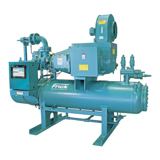
Rotary Screw Compressor Units
Models: 36, 42, and 60
This manual contains installation, operation, and maintenance
instructions. Read thoroughly before beginning installation. Failure
to follow these instructions may result in personal injury or death,
damage to the unit, or improper operation.
Check www.FrickCold.com for the latest version of this publication.
Form 070.700-IOM (MAR 2021)
Installation–Operation–Maintenance
File:
Replaces:
Dist:
HPS
All Refrigerants
Service Manual–Section 070
Nothing
3, 3a, 3b, 3c
Advertisement
Table of Contents
Troubleshooting

Related Manuals for Frick HPS 36


Summary of Contents for Frick HPS 36
- Page 1 Form 070.700-IOM (MAR 2021) Installation–Operation–Maintenance File: Service Manual–Section 070 Replaces: Nothing Dist: 3, 3a, 3b, 3c Rotary Screw Compressor Units All Refrigerants Models: 36, 42, and 60 This manual contains installation, operation, and maintenance instructions. Read thoroughly before beginning installation. Failure to follow these instructions may result in personal injury or death, damage to the unit, or improper operation.
-
Page 2: Table Of Contents
070.700-IOM (MAR 21) HPS Rotary Screw Compressor Units Page 2 Installation - Operation - Maintenance Contents General Information Quantum ™ HD EZ‑COOL ™ liquid injection adjustment procedure ..............25 Preface ................3 Solenoid control ............25 Design limitations .............. 3 EZ Cool status ............ -
Page 3: General Information Preface
It is most important that these units be correctly applied Transit damage claims to an adequately controlled refrigeration system. Consult your authori zed Frick representative for their expert guid- All claims must be made by consignee. This is an ICC ance in this determination. - Page 4 Rotary screw compressor serial numbers are defined by Notice the following information: When inquiring about the compres sor or unit, or order- Example: 10240A90000015Z ing repair parts, provide the model, serial, and FRICK sales order numbers from these data plates. Plant Decade Month Year...
-
Page 5: Installation
(68) (54) (54) (445) (334) (334) ance for a trouble-free installation. Use only the certified general arrangement drawings from Frick to determine the (136) (95) (95) (667) (556) (556) mounting foot locations and to ensure appropriate clear- ances around the unit for ease of operation and servicing. -
Page 6: Removing The Skid
070.700-IOM (MAR 21) HPS Rotary Screw Compressor Units Page 6 Installation section installed, because this may result in damage to the Caution com pressor. Bump the motor to check for correct com- pressor rotation. After verifica- Figure 4: Motor tunnel Never move the unit by pushing or forking against tion, install disc drive spacer, as the separat or shell or its mounting supports. -
Page 7: Holding Charge And Storage
6. See Table 3 for torque values for the disc pack lock- nuts. Hold the bolts in place while the locknuts are The Frick oil charge shipped with the unit is the best torqued. suited lubricant for the conditions specified at the 7. -
Page 8: Oil Heater(S)
(see Figure 7). Using a pressure-type pump and the ap- propriate Frick oil, open the drain valve and pump oil into tion of the system. the separator. -
Page 9: Thermosyphon Oil Cooling (Tsoc)
HPS Rotary Screw Compressor Units 070.700-IOM (MAR 21) Installation Page 9 Thermosyphon oil cooling (TSOC) System operation Liquid refrigerant fills the cooler shell-side up to the Ther- The refrigerant for TSOC (on a high pressure package) is mosyphon receiver liquid level. piped from the high side of the cascade system. -
Page 10: Liquid Injection Oil Cooling (Optional)
The customer must supply adequate water connec- Liquid injection oil cooling tions. Determine the size of the oil cooler supplied with the unit, as outlined on the Frick P&I diagram and general (optional) arrangement drawings. The water or glycol supply must be The liquid injection system provided on the unit is self- sufficient to meet the required flow. -
Page 11: Economizer (Optional)
HPS Rotary Screw Compressor Units 070.700-IOM (MAR 21) Installation Page 11 Economizer (optional) Figure 13: Shell and coil economizer system The economizer option provides an increase in system SUCTION capacity and efficiency by subcooling liquid from the INTERMEDIATE PRESSURE condenser through a heat exchanger or flash tank before GAS TO COMPRESSOR HV-2 it goes to the evapora tor. -
Page 12: Economizer Load Balancing
When the installer, unless a variable speed drive (VSD) pack- one compressor reduces operating speed to the point age is pur chased separately from Johnson Controls-Frick. that the economizer output on the control panel turns Drive packages consist of:... -
Page 13: Current Transformer (Ct) Ratios
HPS Rotary Screw Compressor Units 070.700-IOM (MAR 21) Installation Page 13 Figure 17: VSD wiring diagram Figure 18: Point-to-point wiring diagram VARIABLE-SPEED DRIVE • One compressor is supplied. In addition to the compres- Current transformer (CT) ratios sor, the current transformer (CT) and CPT secondaries are wired as shown in the previous Figure. -
Page 14: Mini Mum Burden Ratings
This is a function of the distance between the motor starting package and the compressor unit. Table 7: Minimum CT burden ratings Burden Maximum distance from rating Frick panel ANSI Using # Using # Using # 14 Awg 12 Awg 10 Awg B-0.1... -
Page 15: Installation Of Electronic Equipment In An Industrial Environment
NEC code and any other applicable codes. tronic control panel from other equipment in the plant that With exclusion of the three phase wire sizing, use Frick generate EMI. See following figure. drawing 649D4743 as a reference for correctly sizing con- trol wires and other wiring specifications. -
Page 16: Grounding
(see Figure 21). Driving a ground stake at the electronic control may also Johnson Controls-Frick requires that the ground conductor meet the following: cause additional problems because other equipment in the plant on the same circuits may ground themselves to the •... -
Page 17: Considerations
All national and local codes must be followed for conduit with regard to materials, spacing and grounding. In ad- Drive dition, Johnson Controls‑Frick requirements must be fol‑ lowed where they exceed or match national or local codes. Conversely, there is no allowance for any practices that are substandard to what is required by national or local codes. -
Page 18: Wiring Practices
070.700-IOM (MAR 21) HPS Rotary Screw Compressor Units Page 18 Installation manufacturer's recommend or provide prepunched conduit Notice connections. You may also be negating the NEMA rating of the enclosure. When in doubt contact the factory or use threaded metallic or threaded PVC coated metallic conduit. Drilling can cause metal filings to land on the electronics and create a short circuit when powered is applied. -
Page 19: Communications
Quantum HD panel. With a UPS system providing ™ shutdown protection for a Frick Quantum panel, the panel may not see the loss of the 3-phase voltage on the motor because the UPS may prevent the motor starter contac- tor from dropping out. - Page 20 070.700-IOM (MAR 21) HPS Rotary Screw Compressor Units Page 20 Installation • Manual – The compressor needs a manual restart after clearing the 3-phase bus fault. If the local power distribution system is unstable or prone to problems there are other potential solutions to satisfy these problems.
-
Page 21: Operation
HPS compressor • Suction flange is ANSI B16.1 Class 400. Discharge flange is ANSI B16.1 Class 600. The Frick HPS rotary screw compressor uses mating • Integral suction strainer. asymmetrical profile helical rotors to provide a continuous flow of vapor and is designed for primarily high-pressure Compressor lubrication system applications. -
Page 22: Compressor Oil Separation System
070.700-IOM (MAR 21) HPS Rotary Screw Compressor Units Page 22 Operation For cascade and heat pump packages, the cold-start Notice valve is equipped with a large spring that creates 30 psi of pressure in the oil separator (above suction pressure), for For alarm descriptions and shutdown or cutout pa- lubrication of the compressor. -
Page 23: Capacity Regulation And Fixed Volume Ratio Vi
HPS Rotary Screw Compressor Units 070.700-IOM (MAR 21) Operation Page 23 Capacity regulation and fixed Single-port liquid injection volume ratio Vi The single-port liquid injection system is desig ned to per- mit liquid refrigerant injection into one port on the com- The design without a moveable slide valve under the ro- pressor at any given moment and operates as outlined. -
Page 24: Low Ambient Operation
You must perform the initial start-up under the super vision thermal expansion valve adjustment for the correct of a Johnson Controls-Frick authorized start-up represen- oil flow by using the discharge temperature is not tative, to prevent voiding the compressor warranty. Before possible. -
Page 25: Quantum ™ Hd Ez-Cool ™ Liquid Injection Adjustment
(4- EZ cool PI control 10mA) signal. This is the standard valve type for Frick packages and includes valves like the Danfoss modulat- [Setpoint] - Enter the value that you wish to control to. -
Page 26: Operation Of Danfoss Liquid Injection Valve
070.700-IOM (MAR 21) HPS Rotary Screw Compressor Units Page 26 Operation Operation of Danfoss liquid Figure 32: Parameter list example ( i 08) injection valve Figure 30: ICAD – Acknowledge and save change of value of a param- eter. – To exit from the Parameter list and return to the display of opening degree (OD), keep the push button activated for 2 s. -
Page 27: Reset To Factory Setting
HPS Rotary Screw Compressor Units 070.700-IOM (MAR 21) Operation Page 27 Table 8: ICM alerts 2. Decrease the VFD speed by 100 rpm increments and physically check the entire package for elevated en- Description Comments ergy at each stage until the minimum speed range is alarm reached. - Page 28 070.700-IOM (MAR 21) HPS Rotary Screw Compressor Units Page 28 Operation Table 9: Parameter list Description Display Min. Max. Factory Unit Comments name setting Gray shading indicates standard setting ICM OD ICM valve Opening Degree is displayed during normal operation. (Opening Degree) Running display value (see j01, j05).
-
Page 29: Maintenance General Information
HPS Rotary Screw Compressor Units 070.700-IOM (MAR 21) Maintenance Page 29 Maintenance ingestion of some refrigerant liquid of any compressor type available today, they are not liquid pumps. Make certain to maintain adequate superheat and correctly General information size suction accumulators to avoid dumping liquid re- frigerant into compressor suction. -
Page 30: Oil Filter (Of-1) Cartridge Style
8. Evacuate (pull a vacuum on) the filter canister to elimi- the unit. nate non-condensibles. Oil filter (OF-1) cartridge style 9. Fill the canister with new Frick refrigeration oil as needed. HPS compressor units are furnished with one main oil 10. Open outlet service valve and leak test. -
Page 31: Coalescer Filter Element(S)
Notice 3. Close the suction and discharge service valves; also close the liquid-injection and economizer service Use of filter elements other than Frick may cause valves, if applicable. warranty claim to be denied. 4. Slowly vent the separator to low-side system pressure 1. -
Page 32: Maintenance Schedule
Using a also the liquid injection and economizer service valves, pressure-type oil pump and appropriate Frick oil, open if applicable. the drain valve and fill the separator until the oil level is 13. -
Page 33: Maintenance Program
Notice on forms and labels and send promptly to the lab for results. The Frick oil charge shipped with the unit is the best suited lubricant for the conditions specified at the Operating log time of purchase. If there is any doubt due to the re-... - Page 34 070.700-IOM (MAR 21) HPS Rotary Screw Compressor Units Page 34 Maintenance Table 11: Relubrication interval/instructions for WEG electric motor WEG Relubrication interval W40 platform and ODP NEMA premium motors. Excludes W50 and W60 platforms Drive Sync. Frame size Grease Amount Interval Service cycle - ball bearings ( g )
-
Page 35: Motor Bearings
HPS Rotary Screw Compressor Units 070.700-IOM (MAR 21) Maintenance Page 35 Motor bearings When an operating problem develops, compare all operat- ing information on the main operating screen with normal Follow the motor manufacturer’s maintenance operating conditions. If there is maintained operating log, recommenda tions for lubrication. -
Page 36: Servicing The Cold-Start Valve (580 Psig Dwp Only)
070.700-IOM (MAR 21) HPS Rotary Screw Compressor Units Page 36 Maintenance Servicing the cold-start valve If the bonnet is under pressure from the spring (15) after all the screws have been loosened by 0.315 in (8 mm), the (580 psig DWP only) valve can sustain damage. -
Page 37: Replacing Pressure Transducers
HPS Rotary Screw Compressor Units 070.700-IOM (MAR 21) Maintenance Page 37 Table 14: Pressure transducer conversion data Notice Sensor 800 psi Voltage Range (psig) Recover or transfer all refrigerant vapor, in ac- High cordance with local ordinances, before opening to atmosphere. -
Page 38: Temperature Sensor
070.700-IOM (MAR 21) HPS Rotary Screw Compressor Units Page 38 Maintenance Temperature sensor Replacement 1. Shut off control power. Troubleshooting 2. Remove DIN connector plug from transmitter. Confirm the setup of the channel on the calibration or See Figure 39. analog board #1 setup screen. -
Page 39: Replacement
Main oil injection valve may be closed. Open valve. Main oil injection valve may be open too far. Adjust. Bearing damage or excessive wear. Contact Frick Factor or Frick service. Coupling loose on shaft. Tighten coupling. Replace if damaged. If motor or compressor have been reinstalled, check that installation done according to 070.660-SM... -
Page 40: Troubleshooting The Liquid Injection Oil Cooling System
070.700-IOM (MAR 21) HPS Rotary Screw Compressor Units Page 40 Maintenance Troubleshooting the liquid injection oil cooling system Symptom Probable causes and corrections High oil temperature Insufficient liquid supply. Check receiver level. Check strainer. Suction superheat too high. Correct system problem. Liquid strainer blocked. - Page 41 HPS Rotary Screw Compressor Units 070.700-IOM (MAR 21) Maintenance Page 41 Figure 41: HPS Compressor port locations Vi ratio COMPRESSOR OPERA TES ON AND IS COMPA TIBLE WITH THE FOLLOWING REFRIGERANTS: R22, R23, R32, R50, R123, R125, R134a, R142b, R170, R218, R236fa, R245fa, R290, R40A, R407C, R410A, R507, R508, R508B, R600, R600A, R717 , R728, R729, R744, R1150, AMMONIA,...
- Page 42 070.700-IOM (MAR 21) HPS Rotary Screw Compressor Units Page 42 Maintenance Figure 42: PID example for a CO 2 cascade compressor package CV-1 SUCTION VALVE SHIPPED LOOSE PALL R744 RELIEF VALVES SHIPPED LOOSE. THE R744 (CO2) RELIEF VALVES SHOULD BE LOCATED OUTDOORS 3/8 OD WITH NO DOWNSTREAM PIPING.
- Page 43 HPS Rotary Screw Compressor Units 070.700-IOM (MAR 21) Maintenance Page 43 Figure 43: PID example for a heat pump package COOLING LOAD HIGH SIDE CV-1 SUCTION VALVE SHIPPED LOOSE PALL 3/8 OD CAPACITY CONTROL YY-1 CAPACITY NV-3 ENERGIZED 100% DE-ENERGIZED SD-2 SC-5 SB-3...
-
Page 44: Operating Log Sheet
Forms 070.700-IOM (MAR 21) HPS Rotary Screw Compressor Units Page 44 Forms Operating log sheet... -
Page 45: Hps Compressor Prestart Checklist
The installer must check and complete the following items before the arrival of the Frick Field Service Supervisor. Details on the checklist can be found in this manual. Certain items on this checklist are reverified by the Frick Field Service Supervisor before the actual start-up. -
Page 46: Start-Up Report
U45 Prog. Ver. ________ Date ___________P/N ________________________ Harmonic Filter Serial # __________________ Prog. Ver. ________ Date ___________P/N ________________________ Frick Interface Serial # ___________________ Prog. Ver. ________ Date ___________P/N ________________________ CT Location Checked CT Phase ______ CT Ratio ______ Transition Time _________ DBS Ver.# _____________... - Page 47 High Level Shutdown Delay ________ Sec Low Oil Level Delay ________ Sec Hot Gas Bypass _________ % Oil Pump Lube Time Before Starting ________ Sec Power Assist _________ Sec Dual Pump Transition Time ________ Sec Page 3 Unit Serial # Frick Order No:...
- Page 48 Max Slide Valve Timer _______ 1/10 Sec High Compressor Oil Pressure ________________ Max Discharge Pressure ___________ PSI Shutdown ____PSI Delay ____ Sec Max Discharge and Oil Temp ________°F Unit Serial # Frick Order No: P and ID Setpoints Name _________________ __________ _________________...
- Page 49 HPS Rotary Screw Compressor Units 070.700-IOM (MAR 21) Forms Page 49 Communications Compressor ID ______ Comm 1 Comm 2 Comm 3 Baud Rate ________ Baud Rate __________ Baud Rate ___________ Data Bits _________ Data Bits ____________ Data Bits ____________ Stop Bits _________ Stop Bits ___________ Stop Bits ____________ Parity ___________...
-
Page 50: Vibration Data Sheet
070.700-IOM (MAR 21) HPS Rotary Screw Compressor Units Page 50 Forms Vibration data sheet Date: __________________________________________ sales order number: _________________________________ End user: _______________________________________ installing contractor: ________________________________ Address: __________________________________________ service technician: __________________________________ ___________________________________________________ ___________________________________________________ Equipment id (as in microlog): _____________________________ Compressor model number: __________________________________ Compressor serial number: ___________________________________ Unit serial number: __________________________________________ National board number: ______________________________________... - Page 51 HPS Rotary Screw Compressor Units 070.700-IOM (MAR 21) Index Page 51 Index Symbols cooling water, 10 CoolWare, 6 3‑phase ground, 17 filter assembly, 30 coupling hubs, 6 3‑phase supply, 17 filter canister, 30 CPT, 13 filter cartridge, 30 crane, 5 filter elements, 8,30,31 CT, 13 flash gas, 12...
- Page 52 070.700-IOM (MAR 21) HPS Rotary Screw Compressor Units Page 52 Index liquid injection, 23 oil level transmitter, 39 oil pump, 21 Alarms, 26 oil quality, 33 oil pump coupling, 7 analog input signal, 26 operating log, 33 oil pump starter, common digital alarm, 27 pressure transducers oil sampling valve, 33...
- Page 53 HPS Rotary Screw Compressor Units 070.700-IOM (MAR 21) Index Page 53 shutdowns, 29 operating level, 8 sight glass, 8,22,32 plate and shell oil cooler, 9 single-box control, 12 receiver, 9,10 single‑port liquid injection, 23 thermostatically controlled mixing skip frequencies, 27 valve, 9 slugging, 29 thermosyphon oil cooling, 9...
- Page 54 Form 070.700-IOM (2021-03) Johnson Controls Supersedes: Nothing 100 Cumberland Valley Avenue Subject to change without notice Waynesboro, PA 17268-1206 USA Published in USA • 02/21 • PDF Phone: 717-762-2121 • FAX: 717-762-8624 www.johnsoncontrols.com/Frick © 2021 Johnson Controls - All Rights Reserved...
Need help?
Do you have a question about the HPS 36 and is the answer not in the manual?
Questions and answers