Advertisement
Quick Links
Instruction Manual, 353mm (13.9") Profile Panel Antennas
Bulletin A997-0083—Revision F — February 2014 page 1 of 7
CommScope Infrastructure Academy offers installation training
General
This instruction manual contains all necessary information required to assist in the correct
installation of ARGUS Panel Antennas of 353mm (13.9") width to a 75 – 115mm (3" - 4.5")
diameter pipe when using the mounting kit with clamp bracket. These antennas can be
supplied with either fixed beam downtilt, manually adjustable electrical downtilt or AISG-
compatible remotely controlled electrical downtilt. Mechanical downtilt is also available if
required, depending on the type of mounting kit selected.
Following symbols can be found next to text outlining important information.
Please follow the procedure marked with this symbol precisely.
Non-compliance may lead to damage of the product.
Handy tips when installing product.
Unpacking
Make sure that the antenna and the accessory items listed below are provided and have not
been damaged during transport.
• Antenna
• Mounting kit (mounting kit components for each configuration are shown in Figures
2 and 3).
• Hex key 6mm AF (supplied with adjustable downtilt antennas only).
Mounting Kit
Type
Fixed Downtilt
Mechanical
Downtilt
Tilt range
Mounting
Bracket
Spacing
Dim A (Fig 4)
Table 1: Mounting Kit Part Numbers for Different Antennas
Do not install near power lines. Power lines,
telephone lines, and guy wires look the same.
Assume any wire or line can electrocute you.
Argus
600mm – 870mm
870mm – 1200mm
(23.6" – 34.3")
Antennas
F-042-GL-E
T-095-GL-E
0° -15° in 3° steps
480mm (18.9")
Installation Instructions
®
(34.3" – 43.3")
Antennas
F-042-GL-E
T-045-GL-E
0°, 2° -10° in 1°
steps
716mm (28.2")
Do not install on a wet or windy day or
when lightning or thunder is in the area.
Do not use metal ladder.
1200mm – 1575mm
(43.3" – 62")
Antennas
F-042-GL-E
T-041-GL-E
0° - 12° in 1° steps
976mm (38.4")
Wear shoes with rubber soles and heels.
Wear protective clothing including a
long-sleeved shirt and rubber gloves.
1575mm – 2700mm
(62" – 106.3")
Antennas
F-042-GL-E
T-029-GL-E
0° - 8° in 1° steps
1400mm (55.1")
Advertisement

Subscribe to Our Youtube Channel
Related Manuals for CommScope Argus CVVPX


Summary of Contents for CommScope Argus CVVPX
- Page 1 Argus Instruction Manual, 353mm (13.9”) Profile Panel Antennas Bulletin A997-0083—Revision F — February 2014 page 1 of 7 CommScope Infrastructure Academy offers installation training General This instruction manual contains all necessary information required to assist in the correct installation of ARGUS Panel Antennas of 353mm (13.9") width to a 75 – 115mm (3" - 4.5") diameter pipe when using the mounting kit with clamp bracket.
-
Page 2: Installation Instructions
Instruction Manual, 353mm (13.9”) Profile Panel Antennas Bulletin A997-0083—Revision F — February 2014 page 2 of 7 Installation Instructions Ensure a torque spanner is used when tightening fasteners, see the mounting kit diagrams on the following pages for the correct torque recommendations. Ensure antenna is installed with the connectors at the bottom. - Page 3 Instruction Manual, 353mm (13.9”) Profile Panel Antennas Bulletin A997-0083—Revision F — February 2014 page 3 of 7 (21ft.lb) (28ft.lb) (70ft.lb) Figure 2: Typical Exploded Assembly for Upper Mounting Bracket using Clamp Bracket (21ft.lb) (28ft.lb) (70ft.lb) Figure 3: Exploded Assembly for Lower Mounting Bracket using Clamp Bracket (This configuration should also be used for the upper Mounting Bracket when 0°...
- Page 4 Instruction Manual, 353mm (13.9”) Profile Panel Antennas Bulletin A997-0083—Revision F — February 2014 page 4 of 7 OPTIONAL: THE TILT ARM AND EXTRA HARDWARE CAN BE STOWED IN THE POSITION SHOWN WHEN IN 0° DOWNTILT CONFIGURATION USING A CLAMP BRACKET. Figure 4: Typical Example of Upper Bracket Placement for Various Downtilts Operation of Antennas Fixed Downtilt...
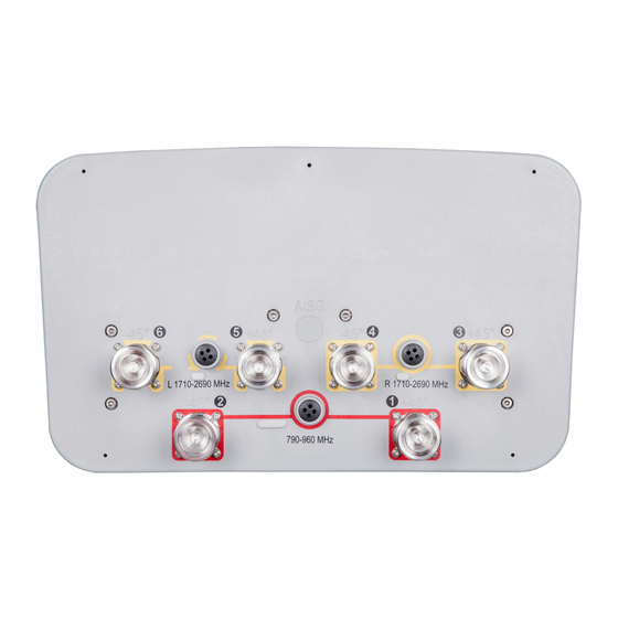
- Page 5 Instruction Manual, 353mm (13.9”) Profile Panel Antennas Bulletin A997-0083—Revision F — February 2014 page 5 of 7 Each RF and/or AISG port on the antenna is numbered and identified in Port and Band accordance with AISG Standard “AISG Antenna Port Color Coding Identification v1.0”.
- Page 6 Instruction Manual, 353mm (13.9”) Profile Panel Antennas Bulletin A997-0083—Revision F — February 2014 page 6 of 7 End Cap Layout for Typical Antennas Tilt adjust and scale (Band 1) Tilt adjust and scale Tilt adjust and scale (Band 2) (Band 3) Figure 5: Typical 6-port (CVVPX) with internal bias tee on Port 1.
- Page 7 Hinweis: CommScope lehnt jede Haftung oder Verantwortung für Schäden ab, die aufgrund unsachgemäßer Installation, Überprüfung, Wartung oder Demontage auftreten. Atenção: A CommScope abdica do direito de toda responsabilidade pelos resultados de práticas inadequadas e sem segurança de instalação, inspeção, manutenção ou remoção.
Need help?
Do you have a question about the Argus CVVPX and is the answer not in the manual?
Questions and answers