Advertisement
27-2200-3
Revision C,
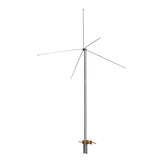
High Band Ground Plane Antenna
ASP7A
GENERALINFORMATION
This antenna is supplied to operate satisfactorily within the
frequency range(s) specified on the carton label. Some mod-
els require cutting of the radiator and/or radials in accordance
with the charts located on page 2. If the antenna is to be used
over a range of frequencies, the element lengths should be
chosen for mid-range or favor the element lengths for the most
used, or the frequency requiring the greatest range.
INSTALLATION INSTRUCTIONS
1.
Select antenna location and route cable from set to an-
tenna.
2.
Loosen mounting nut and assemble radials to hub as
shown in Figure 1. Tighten jam nuts and lockwashers
against hub to secure the radials. Retighten mounting
nut.
3.
Connect cable to antenna (accepts PL-259).
Some models are supplied with cable and connector for
the antenna end. Radio end connector is not supplied.
4.
Mount antenna onto 1/2" to 3/4" pipe, or up to 1-3/8" O.D.
tubing (not supplied) with "U" bolt, lockwashers and hex
nuts provided.
5.
Secure cable to mounting pipe with strap or plastic tape
to avoid strain on cable connections.
The use of a PTFE or similar lubricant on the
threaded portions of the antenna, prior to assem-
bly, will protect from weather and ease future dis-
assembly.
SAFETY NOTICE
The installation, maintenance, or removal of an antenna
requires qualified, experienced personnel. CommScope
installation instructions are written for such installation
personnel. Antenna systems should be inspected once a
year by qualified personnel to verify proper installation,
maintenance, and condition of equipment.
CommScope disclaims any liability or responsibility for the
results of improper or unsafe installation practices.
It is recommended that transmit power be turned off
when the field installation is performed. Follow all
applicable safety precautions as shown on this page.
Do not install near power lines. Power lines,
telephonelines,andguywireslookthesame.
Assume any wire or line can electrocute you.
www.commscope.com
© 2016 CommScope, Inc. All rights reserved.
Visit our website at www.commscope.com or contact your local CommScope representative or BusinessPartner for more information.
All trademarks identified by ® or ™ are registered trademarks or trademarks, respectively, of CommScope, Inc. 27-2200-3 C (05/16)
May 2016
Do not install on a wet or windy day or when
lightning or thunder is in the area. Do not use
metal ladder.
Note:
Remove caplug
before cutting
radiator. Replace
caplug when finished
cutting radiator.
Hub
Jam Nut
Split Lockwasher
Mounting
Bracket
Split
Lockwashers
Hex Nuts
Figure 1. Assembling the Antenna.
Wear shoes with rubber soles and heels.
Wear protective clothing including a long-
sleeved shirt and rubber gloves.
Replacement Radiator
(19-477-5)
Radiator Length
"A"
Replacement Radial
(19-322-3)
Radial Rods
"U" Bolts
Internal
Tooth
Lockwasher
Mounting Nut
(continued on page 2)
Page 1 of 2
Advertisement
Table of Contents

Related Manuals for CommScope ASP7A


Summary of Contents for CommScope ASP7A
- Page 1 © 2016 CommScope, Inc. All rights reserved. Visit our website at www.commscope.com or contact your local CommScope representative or BusinessPartner for more information. All trademarks identified by ® or ™ are registered trademarks or trademarks, respectively, of CommScope, Inc. 27-2200-3 C (05/16) Page 1 of 2...
- Page 2 © 2016 CommScope, Inc. All rights reserved. Visit our website at www.commscope.com or contact your local CommScope representative or BusinessPartner for more information. All trademarks identified by ® or ™ are registered trademarks or trademarks, respectively, of CommScope, Inc. 27-2200-3 C (05/16) Page 2 of 2...
Need help?
Do you have a question about the ASP7A and is the answer not in the manual?
Questions and answers