
Related Manuals for Wohler iVAM1-1


Summary of Contents for Wohler iVAM1-1
-
Page 1: User Guide
1RU Multi-Channel Audio Video Monitor User Guide Part Number 821829, Revision B... - Page 2 In no event will Wohler Technologies, Inc. be liable for direct, indirect, special, incidental, or consequential damages resulting from any defect in the hardware, software, or its documentation, even if advised of the possibility of such damages.
-
Page 3: Table Of Contents
TABLE OF CONTENTS Table of Contents User Guide ..................1 TABLE OF CONTENTS ................3 Table of Contents ................... 3 CHAPTER 1: Installation ............... 6 Introduction ....................6 Overview .................... 6 Safety ......................6 Instructions ..................6 Safety Symbols ..................7 Mounting..................... - Page 4 Dante Legal Disclosures................62 APPENDIX D: Ravenna (ZMAN) Setup ..........63 Introduction ....................63 What is in the iVAM1-1 for Ravenna ..............63 RAVENNA-Compatible Talker/Listener............ 63 AVB Ethernet Features ................ 63 Configuring the AOIP Merging Option Card............64 Getting Started | General Settings ............65 Getting Started | PTP ................
- Page 5 ZMAN Updating .................. 73 APPENDIX E: API Documentation ............74 Introduction ....................74 API ......................74 Body Content for SDI/SMPTE-2022-6/ SMPTE-2110......... 74 Body Content for MADI................ 74 Body Content for Analog..............74 Body Content for AES ................. 75 Status Codes ....................75 Page 5...
-
Page 6: Chapter 1: Installation
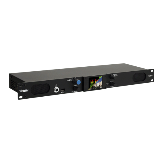
Either 8 or 16 channel meters can be displayed. The iVAM1-1 includes two 3G SDI inputs and it can monitor both video and audio from them. Optional modules will allow decoding of an additional SDI input, MADI, AES3, TOSLINK, SMPTE 2110, and SMPTE 2022-6 streams. -
Page 7: Safety Symbols
of time. 10. Refer all servicing to qualified service personnel. Servicing will be required under all of the following conditions: a. The equipment has been damaged in any way, such as when the power- supply cord or plug is damaged. b. -
Page 8: Sympathetic Vibration
Sympathetic Vibration Sympathetic vibration from other equipment (cables, etc.) in the rack may be serious enough to interfere with the unit’s sound quality. If you experience sympathetic vibrations, use thin card stock, felt, foam, or weather-stripping between the vibrating surfaces. Tie loose cables securely with cable ties. Mechanical Bracing The 1RU chassis is securely attached to the front panel. -
Page 9: Chapter 2: Local Operation
CHAPTER 2: Local Operation Operation The iVAM1-1 can be operated easily and simply from controls on its front panel, as described in this chapter. It may be accessed remotely in two ways, via the Wohler Web GUI for administrative purposes or by third party equipment via Application Programming Interface (API) commands. - Page 10 8. USB: This USB 2.0 Type A connector allows you to use a flash drive (not supplied) to perform software updates and copy system configurations to another iVAM1-1 or to a PC. Refer to Appendix A of this manual to learn about performing a software update.
-
Page 11: Rear Panel
Chapter 4 of this manual. Third party equipment, connecting to the iVAM1-1 via a LAN plugged into this port and using an API commands, can view and change product options, as well. This API is described in Appendix E of this manual. - Page 12 through. A software license must be installed for this input to function. Refer to the System Setup section in Chapter 4 and to Figure 4-7 to install software licenses. 6. MADI Fiber SFP: (optional) This input module accepts an optical AES10 64-channel MADI input signal at 48 kHz sample rate.
- Page 13 Wohler Technologies Technical Service. e. SMTPE 2110 or 2022-6 Receiver: This uses Multi-Mode 850 NM, LC fiber connectors. It allows the iVAM1-1 to monitor SDI audio transmitted in real time over Ethernet. You must use the emSET configuration software to set up this option. It is available from Wohler Technologies Technical Service.
- Page 14 Option card. The source of these signals is the monitored audio channels as shown on meters 1 - 8. Tascam cables may be used, and can be purchased by contacting Wohler Sales. Refer to Figure 2-6 for the pinout of this connector.
- Page 15 Figure 2-6: Analog DB-25F Input and Output Connections Pair 1 Pair 2 Pair 3 Pair 4 15. AoIP SFP Module Cage (optional): This provides a location in which to insert the AoIP Module supplied with the OPT-DANTE (iVAM) and OPT RAVENNA 64 options.
-
Page 16: Sfp-2022-6 / Sfp-2110 Address Setup
192.168.39.215 iVAM-1 with SFP-2022-6 / SFP-2110 The optional SFP-2022-6 or SFP-2110 module furnished by Wohler Technologies is manufactured by Embrionix and comes from the factory with a default IP address. To integrate it into your digital network, you need to set its address to the source to be monitored. -
Page 17: Channel Meters And Touch Operations
Channel Meters and Touch Operations The audio mixer terminology of “solo” is used in this manual when referring to muting all but a specific audio channel or pair. Audio meters are displayed on touchscreen LCD display(s) in up to 8 channel pairs, as shown in Figure 2-8. - Page 18 Mute / Un-Mute Selection: A violet box surrounds any channel pair that is muted. Typically, when the iVAM1-1 is first powered, all of the channel pairs are muted. Touching a muted channel pair un- mutes it and removes the violet box. Muting and un-muting by touching is an alternate action function.
-
Page 19: Video Screen
Video Screen Pressing the Source knob alternates between the Video Screen and the Meter Screen on an SDI source. Information about the signal can be superimposed over the upper part of the video image. The Video Info selection in the Unit Config Menu determines whether this information is always displayed, never displayed, or is only displayed for the first 5 or 10 seconds after switching to the video screen. -
Page 20: Menu / Option Touchscreen
Menu / Option Touchscreen You may set most options or view a variety of system information using the self- contained menus. To access this, touch the Menu button which appears on the right of the level meter screen. Figure 2-11 is a diagram of the menu arrangement, a tree showing how to reach any menu from the Main Menu. -
Page 21: Main Menu
Main Menu Touching the Menu button on the Audio Meters screen will access the Main Menu. Alternatively, especially when monitoring the video program, you may access the Main Menu by holding the Source knob pressed for two seconds. The Main Menu is shown in Figure 2-12. Figure 2-12: Main Menu Audio Meters Touching the Audio Meters selection on the Main Menu screen simply returns you... -
Page 22: Speaker Options
Touching the Speaker Options selection on the Unit Settings Menu screen proceeds to the Speaker Options screen. The controls on this screen affect various characteristics of the monitored audio as heard on the iVAM1-1. This screen is shown in Figure 2-14. -
Page 23: Meter Scales
Meter Scales Touching the Meter Scales button on the Unit Settings Menu displays the Meter Scales screen as shown in Figure 2-15. The controls on this screen select the scale standards as well as the ballistics that will be applied to the audio meters. Figure 2-15: Meter Scales Screen The controls function as follows: 1. - Page 24 Table 2–4: Meter Limits and References Default Color Default Ballistics Default Bounds Scale Bottom Limit Top Limit Reference Lower Upper Float -72 dBFS 0.0 dBFS 0 dBFS = 0 dBFS -30 dBFS -20 dBFS Type I VU -53 dBr +5.5 dBr -15 dBFS = 0 dBr -5 dBr 0 dBr...
-
Page 25: Unit Configuration
3. AES termination: AES signals should have one and only one termination. This termination should physically be at the last destination of an AES coax cable. If the iVAM1-1 is the last connection in a series of AES connections, then its terminations should be turned on. A symptom of too many terminations (or no termination) is that no signal appears to be present on the AES input. -
Page 26: Phase Configuration
reminder. Touch Back to exit this menu. Phase Configuration Touching the Phase Config selection on the Unit Settings Menu proceeds to the Phase Config Menu. This menu is shown in Figure 2-18. Figure 2-18: Phase Configuration Menu The controls function as follows: 1. -
Page 27: Hdmi Settings
(EDID) to disclose their capabilities to the video source. The iVAM1-1 can use this information to ensure its compatibility with the HDMI Monitor. If you decide that you do not want the iVAM1-1 to receive this information, set this switch to Off. By default this switch is set to On. -
Page 28: Meter Mode
Meter Mode Touching the Meter Mode selection on the Unit Settings Menu proceeds to the Meter Mode Menu. This menu is shown in Figure 2-20. Figure 2-20: Meter Mode Menu Meter Mode Cancel & Exit Save & Exit 8 Channel Mode The control functions as follows: 1. -
Page 29: Source Select
This screen also shows sources which are unlicensed and therefore nonfunctional. These sources are shown in a gray color. To license these sources so that they may be used, contact Wohler Technologies. Figure 2-21 shows the Source Select Menu. - Page 30 AoIP CH 49-64 Valid hardware is required Feature is not supported or requires valid hardware. Please call at +1-510-870-0810 or email at support@wohler.com. Thank you! Input source: Analog/DB25-1/Slot-0 Back Touch Back to return to the Source Select menu or touch Menu to return to the Main Menu.
-
Page 31: System Options Menu
System Options Menu Touching System Options in the Main Menu proceeds to the System Options menu, which is an intermediate menu leading to other screens. This menu is shown in Figure 2-23. Figure 2-23: System Options Menu Touch Menu to exit this menu. Network Settings Touch the Network Settings selection on the System Options Menu displays the Network Settings menu as shown in Figure 2-24. - Page 32 Figure 2-25: Network Configuration: Setting Change 2. Touch the digits to be entered and then touch the Enter button. The Clear button may be touched to erase any mistyped digits. 3. Now repeat steps 1 and 2 until you have replaced all of the necessary digits. 4.
-
Page 33: System Reboot
You wish to Reboot the System? If you have any doubt as to whether you should press Yes, press Back or No instead, and contact Wohler Technical Service for advice. Pressing Back or No will return you to the System Options menu. Page 33... -
Page 34: System Update
Touching the System Update selection in the System Options Menu displays System Update screen as shown in Figure 2-28, showing the current software version of the product. To update the system software locally from the iVAM1-1 front panel, follow the procedure in the Local Update from the Front Panel section of Appendix A. -
Page 35: Factory Reset
Mac address 28.) If you have any doubt as to whether you should press Yes, press Back or No instead, and contact Wohler Technical Service for advice. Pressing Back or No will return you to the System Options menu. -
Page 36: System Information
System Information Touching the System Details selection in the System Options menu displays the System Details screen as shown in Figure 2-30. This screen lets you view the product Serial Number, Software Version, and various other information. Figure 2-30: System Details Screen The information shown on this screen is read only and cannot be changed. -
Page 37: Chapter 3: Technical Info
CHAPTER 3: Technical Info Table 3–1: iVAM1-1 Specifications Specification Values/Domains Power Requirements 100 VAC to 240 VAC ± 10%, 50/60Hz Power Consumption 65 Watts Dimensions 1.75” x 19” x 5.5” (44mm x 483mm x (H x W x D) 140mm), standard 19” rack mounting Shipping/Net Weight 8 lbs. - Page 38 Specification Values/Domains COAX (such as Belden 1694A): > 150 m Cable/Fiber Length (max) Single-mode fiber: 10 km AES Inputs 8 AES channels on 2 x HD-15 are optional Upgrades Via USB interface SDI Input Termination 75Ω unbalanced AES/EBU Input Termination 75Ω unbalanced AES/EBU/MADI Sampling 48 kHz Rate...
- Page 39 Table 3–2: iVAM1-1 I/O Options Option Part # Description MADI optical fiber transceiver. Multi-Mode, LC SFP-Madi-MM- 829081 (fiber) connectors. SFP module with software Fiber activation key. MADI optical fiber transceiver. Single-Mode, SFP-Madi-SM- 829082 LC (fiber) connectors. SFP module with Fiber software activation key.
- Page 40 Table 3–3: iVAM1-1 Option Cards Option Part # Description OPT-ANLG/TOS Enable monitoring of 8 Analog channels on 829170 (iVAM) DB-25. TOSLINK included. Enable decoding and monitoring of Dante input streams. Includes AoIP card. Enables 2 x OPT-DANTE RJ-45 ports for 2022-7 support (for Dante,...
- Page 41 Figure 3–1: iVAM1-1 Block Diagram Page 41...
-
Page 42: Chapter 4: The Ivam1-1 Web Gui
Web GUI. The iVAM1-1 Web GUI also allows you to have a remote view of the Meter Screen. Refer to the Audio Meters section in this chapter. -
Page 43: Network Connection
GUI. Network Connection When connected to a network, the iVAM1-1 address will need to be changed to another address in order to be compatible with the address assignments for that particular network. Immediately after the host setup is complete, change the iVAM1-1’s address. -
Page 44: Network Setup
Network Setup Make network IP Address changes for the local iVAM1-1 Management (MGMT) Port here. Figure 4–2: Set IP Addresses The procedure for changing the IP Address information is as follows: 1. Use DHCP? Check this box if your network has a DHCP server and you want to use dynamic addressing. -
Page 45: Audio Meters
Audio Meters Click on Audio Meters to remotely display the audio meters of the iVAM1-1. This display is shown in Figure 4-3. Also displayed is the name of the source that the meters are displaying. In Figure 4-3, this is SDI-1. -
Page 46: System Preferences
System Preferences Click on System Preferences to find the Phase Indicator Configuration tab. This is as shown in Figure 4-4. It allows you to select which channel pairs will receive a phase meter on the Metering Screen. Generally, it is useful to monitor the relative phase of stereo pairs. -
Page 47: System
These tabs are explained in the following three sections. System Information This tab displays a variety of information about the iVAM1-1. It is shown in Figure 4-5. This information could be useful to view if you are contacting Wohler Technical Service. -
Page 48: Sfp Information
This tab displays a variety of information about the module inserted into the SFP slot on the rear panel of the iVAM1-1. It is shown in Figure 4-6. This information could be useful to view if you need to ascertain what module, if any, is installed, or if you are contacting Wohler Technical Service. -
Page 49: Licenses
This tab displays the license number for each of the modules or features in the iVAM1-1. It is shown in Figure 4-7. You will use this tab to enter any new license numbers that you purchase. Contact Wohler Sales to obtain new license numbers. -
Page 50: Factory Reset
If you have any doubt as to whether you should perform a Factory Reset, do not click the Initiate Factory Reset button. Contact Wohler Technical Service for advice. Factory Reset will also reset your IP address to the default one. After a Note: Factory Reset, the IP Settings will need to be updated. -
Page 51: Reboot System
The Reboot System function should be used with a bit of caution. It puts the iVAM1-1 out of service for several minutes while it is rebooting, and this may unexpectedly interfere with the use of the product by the remote operator. -
Page 52: Appendix A: Software Upgrades
Introduction This chapter describes how to download a software update file to your computer, transfer it to a USB flash drive and install the updated software into an iVAM1-1. Download the Software The iVAM1-1 software update can be found at http://www.wohler.com, or contact Wohler Customer Support for more information. - Page 53 Figure A-2 - System Update Screen 5. The new software version that is in the flash drive will be shown in the Software Version screen. To cancel the upgrade at this point for any reason, touch Back. To proceed, touch the software version entry in the Software Version screen.
- Page 54 The upgrade will take several minutes, after which the iVAM1-1 will restart. After the system has completed its restart cycle, the Status indicator will turn green and the iVAM1-1 will once again be operational. At this point, you may remove the flash drive.
-
Page 55: Appendix B: Dante Network Setup
On iVAM1-1, the AoIP source can be selected through the Source Select option. The iVAM1-1 is set up at the Wohler factory to be used as a slave rather than a master within the Dante network. Other devices or software, such as a Dante Controller, are expected to be responsible for most device configurations and all audio routing. -
Page 56: What Is In The Ivam1-1 For Dante
Figure B–2: Device View Up to 16 of the 64 AoIP receive channels can be monitored at once in the iVAM1-1. The iVAM1-1 transmits up to 20 channels. 1 to 16 are the monitored channel in prefade mode. -
Page 57: Dante Tm Device Setup
Dante Device Setup The iVAM1-1’s default Dante Device Name is “Wohler- …” followed by the last 6 digits of the Dante port MAC address, as shown in Figure B-3. This name can be changed by the Dante Controller to appear that way on the network, but that will not change the iVAM1-1’s unit name appearing on GUI pages and iVAM1-1 Remote... -
Page 58: Dante Clock Selection
Dante Clock Selection While the Brooklyn’s internal clock is highly accurate, the iVAM1-1 does not have provisions for external sync clocks, such as those that are GPS or media reference (video genlock or audio word clock) based. So it is generally not the best candidate to be the PTP Master Clock (commonly called the “grandfather clock”) for the... -
Page 59: Aes67
AES67 The iVAM1-1 Brooklyn II can be configured for AES67 operation. AES67 operation with Dante is limited to eight or less receive and transmit channels at 48 kHz sample rates. 24 bit linear (L24) encoding and 1 msec packet time are fixed default transmit parameters. - Page 60 Figure B–7: Device View - Network Config Page 60...
-
Page 61: Device Lock
Flows window shown in Figure B-8. Figure B–8: Multicast Device Lock Audinate recently added a feature whereby a remote controller can send a command to lock Dante network device configurations. The iVAM1-1 does not implement the Device Lock command at this time. Page 61... -
Page 62: Dante Firmware Upgrades
Dante Firmware Upgrades Wohler iVAM1-1 monitors ship with current Brooklyn II firmware as of the option installation date. The version information is found in the Dante Controller Device View-Status page. iAM software/firmware is tested with the latest Dante code release. Therefore it is strongly recommended that iVAM1-1 and Dante software/ firmware be updated at the same time to ensure compatibility and support of the latest features. -
Page 63: Appendix D: Ravenna (Zman) Setup
Merging ZMAN Card is virtually plug and play. The iAM rear panel AoIP jack supports 1Gb/s and 100Mb/s Ethernet devices in Ravenna Audio over IP network configurations. iVAM1-1 channel source selections are made by choosing Input Type ‘AoIP’ in the Configuration-Configure Presets page regardless of which AoIP option is installed. -
Page 64: Configuring The Aoip Merging Option Card
The Merging Ravenna card runs specific firmware from Merging and augmented by Wohler for use within the iVAM1-1. The card will not function correctly if the user downloads and installs firmware from any source besides Wohler. The Wohler augmentation includes the ability to support 64 channels. -
Page 65: Getting Started | General Settings
Merging Ravenna configuration page. Also, the ICON of the card will appear in the main part of the Aneman screen. Double Clicking on the ICON also will load the Configuration screen. For browser access, the URL is <Ravenna subnet>.x/advanced/index.html. This brings up the Merging Ravenna configuration page. -
Page 66: Getting Started | Ptp
Getting Started | PTP This tab is shown in the following figure. This configuration page refers to how your Ravenna network is synchronized to clocks. Figure D-2: Getting Started | PTP The elements of this tab are as follows: 1. Global Settings: The default value for PTP a. -
Page 67: Getting Started | Session Sources
a. Lock: This shows if the device is locked to PTP (Locked -Locking - Unlocked) b. Master: This is true or false for the current device. c. GMID: This is the current GrandMasterID (PTP Master) d. Delta (ns): This is the time delta between the device and the PTP master. -
Page 68: Getting Started | Session Sinks
9. Codec: The possible bit rate values are L24, L16, DSD64, DSD64_32, DSD128, DSD128_32, and DSD256. Note that these values are sampling rate dependent. 10.Frame size (samples): This the frame size of the current source. 11.DSCP: The audio DSCP should be set to 34 for RTP AES67 or 46 for RTP Ravenna. -
Page 69: Getting Started | Session Info
7. Ignore RefClk GMID - accept source locked to any PTP master: This feature is useful when you want to connect a stream through Internet (for example with two PTP Masters (GPS) at each location. This allows making of connections with devices locked to different traceable PTP Masters. See RefClk PTP traceable on the Session Sources tab. -
Page 70: Getting Started | Ins/Outs
Getting Started | Ins/Outs This tab allows you to change the name of the specific Inputs and/or Outputs. Figure D-5: Getting Started | Ins/Outs Getting Started | I/O Router This page allows remapping of incoming channels to different internal channel assignments. -
Page 71: Operation
IAM interface for display on meters and speakers, etc. The iVAM1-1 must be set to receive AOIP from the Source Select Front Panel menu or a browser iVAM1-1 GUI. - Page 72 For example, for monitoring 2 SDI sources (four 8 channel Flows), assign two flows to 1-8 and 9-16 and the next SDI signal to 17-24 and 25- 32. Touch the iVAM1-1 AOIP selection menu to select the proper range to monitor, up to 57-64.
-
Page 73: Zman Session Sources
Figure D-8: Session Sources Tab ZMAN Updating The Zman card is pre-initialized with the correct Wohler firmware load. In case of future upgrades, use the following steps: 1. In Aneman, right click the ZMAN entry on the bottom Devices section, and select Maintenance Mode. -
Page 74: Appendix E: Api Documentation
Introduction This appendix discusses ways to use the Application Program Interface (API) to allow third party equipment to remotely access options and settings of the iVAM1-1. It includes specific code examples for commonly used requests. The API uses JavaScript Object Notation (JSON) as its communication language. -
Page 75: Body Content For Aes
Body Content for AES "SourceType": " " Success Response: "unit_name": "iVam", "model": "iVam", "api_version": 1, "message": "Input Source Madi.Coax has been applied successfully", "serial_number": "123456", "status": Failure Response: "action": "For more information about valid data, please see API document.", "status": 422, "message": { "SourceType": "Not a valid choice"...
Need help?
Do you have a question about the iVAM1-1 and is the answer not in the manual?
Questions and answers