
Related Manuals for Wohler iAM-VIDEO-2


Summary of Contents for Wohler iAM-VIDEO-2
-
Page 1: User Guide
2RU, Multi Channel, Touch Screen Audio/Video Monitor User Guide Part Number 821816, Revision B... - Page 2 In no event will Wohler Technologies, Inc. be liable for direct, indirect, special, incidental, or consequential damages resulting from any defect in the hardware, software, or its documentation, even if advised of the possibility of such damages.
-
Page 3: Table Of Contents
TABLE OF CONTENTS Table of Contents User Guide ..................1 TABLE OF CONTENTS................3 Table of Contents .....................3 CHAPTER 1: Installation ................6 Introduction ....................6 Overview....................6 Safety......................6 Instructions ...................6 Safety Symbols..................7 Mounting....................7 Heat Dissipation..................7 Sympathetic Vibration................8 Mechanical Bracing .................8 Electrical Interference ................8 Power ....................8 Compliance .....................8 FCC ......................8 ICES-003 ....................9... - Page 4 System Information................35 CHAPTER 3: Technical Info ..............36 CHAPTER 4: The iAM-VIDEO Web GUI........... 41 Web Browser / Control Device ................. 41 First Time- IP Assignments ................41 Peer-to-Peer Connection ............... 41 Network Connection ................42 Dashboard..................... 43 Configuration – Preset Setup ................44 Configuring Dolby Presets ..............
- Page 5 AVB Ethernet Features ................70 BACH™ Controller Interface..............71 Home Page....................72 Configuration/Device Management ..............72 Controller Cloud..................74 Sync......................75 Source Streams ..................76 Stream Destinations ................... 77 Patch Panel ....................79 Troubleshooting ..................... 80 Ravenna Firmware Upgrades ................80 APPENDIX D: API Documentation ............
-
Page 6: Chapter 1: Installation
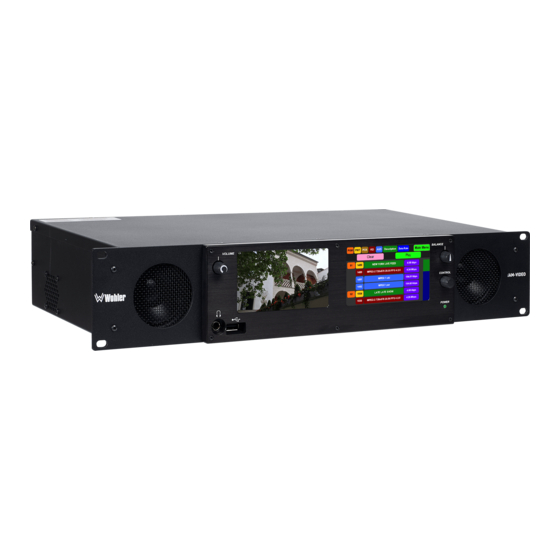
VIDEO-2 includes a 3G SDI SFP module and it can monitor both video and audio from it. An optional module will allow decoding of Dolby D, DD+, and E streams. The iAM-VIDEO-2-MPEG includes an MPEG module, so it accepts MPEG Video transport streams over ASI or IP. Both products have options for VoIP formats including MPEG2/4 TS and SMPTE 2022-6, 3G/HD/SD-SDI, and a growing range of additional I/O options via an SFP interface. -
Page 7: Safety Symbols
Important: By design, this monitor will only plug into a three-prong outlet for your safety. If the plug does not fit into the outlet, contact an electrician to replace the obsolete outlet. 7. Protect the power cord from being walked on or pinched, particularly at plug connection on the equipment and at the socket. -
Page 8: Sympathetic Vibration
proximity to the unit if this temperature is not exceeded. Otherwise, allow a 1RU (1.75”/44.45mm) space above and below the unit for air circulation. Important Heat generated by the class D power amplifiers, power supplies, and other components is vented by slots in the sides and back of the unit. -
Page 9: Ices-003
instruction manual, may cause harmful interference to radio communications. Operation of this equipment in a residential area is likely to cause harmful interference, in which case the user will be required to correct the interference at their own expense. ICES-003 This Class A digital apparatus complies with Canadian ICES-003. -
Page 10: Chapter 2: Local Operation
It may be operated remotely in two ways, via the Wohler Web GUI or by third party equipment via Application Programming Interface (API) commands. -
Page 11: Rear Panel
3. Volume: This controls the speaker and headphone output level for the entire mix. 4. Balance: This controls left/right levels for the stereo mixes. By default, it controls loudspeaker and headphone output, though other options may be set in the Web GUI preferences. - Page 12 Use of another power adapter provided by the user may negate the compliance or cause the monitor to not perform properly. Wohler Technologies cannot accept any responsibility for the outcome in such cases. 2. GPIO: (future implementation) 3.
- Page 13 Ethernet. You must use the emSET configuration software to set up this option. It is available from Wohler Technologies Technical Service. f. SMTPE 2110 Receiver: This uses Multi-Mode 850 NM, LC fiber connectors. It allows the iAM-VIDEO to monitor SDI audio transmitted in real time over Ethernet.
- Page 14 +10dBu broadcast level balanced audio. An optional license key must be purchased to enable this function. Tascam cables may be used, and can be purchased by contacting Wohler Sales. Refer to Figure 2-3 for the pinout of this connector.
-
Page 15: Sfp-2022-6 / Sfp-2110 Address Setup
Figure 2-5: SFP-2022-6 and SFP2110 Network Diagram The optional SFP-2022-6 or SFP-2110 module furnished by Wohler Technologies is manufactured by Embrionix and comes from the factory with a default IP address. To integrate it into your digital network, you need to set its address to the source to be monitored. -
Page 16: Channel Meters And Touch Operations
Channel Meters and Touch Operations The audio mixer terminology of “solo” is used in this manual when referring to muting all but a specific audio channel or subgroup. Since the terms “group” and “subgroup” have different meanings in SDI vs. pro audio, this manual uses the term “cluster”... - Page 17 A square indicates that this is a center channel and will be monitored in both speakers. The symbol shown on channels 7 and 8 in Figure 2-6 indicate that this channel pair is a Dolby bitstream. Refer to the Dolby Zoom section of this chapter.
-
Page 18: Dolby Monitoring Screens
Dolby Monitoring Screens Dolby Zoom Screen Dolby Zoom is a very powerful analysis tool. Much as a camera lens can "zoom" into a single subject of interest out of many, the Dolby Zoom feature lets you quickly "zoom" into a single Dolby bitstream, out of multiple encoded Dolby streams and other channels. - Page 19 intermittent network issues or poor wiring. Occasional errors probably cannot be heard, but this is a diagnostic tool that lets you measure the extent of the problem, if any. Touching the Exit Dolby button returns you to the monitoring screen from which you came.
- Page 20 If a Dolby E stream is being monitored and it has multiple programs, then a Program button appears on the screen, as shown in Figure 2-10. This lets you select which program to monitor. Figure 2-10: Dolby E Screen with Multiple Programs Exit Dolby Program Data Rate...
-
Page 21: Preset Fixed Dolby Screen
Preset Fixed Dolby Screen If it is necessary to monitor a Dolby stream, but it is desired to maintain the Dolby screen all of the time, without using the Dolby Zoom feature, then a Preset can be set up to do this. This screen appears as shown in Figure 2-12. Refer to the Configure Presets section of Chapter 4 to set up a preset such as this. -
Page 22: Menu / Option Touchscreen
Menu / Option Touchscreen By far, most of the option settings are performed using the Web-based GUI software. However, there are a few commonly used setting and information screens that are available locally in the iAM-VIDEO using the Main Menu which appears on the left screen. -
Page 23: Main Menu
Main Menu To access the submenus, touch one of the selector buttons presented on the screen, as shown in Figure 2-15. To return to the Audio Meters display, touch the Audio Meter selector button. Figure 2-15: Main Menu The function of each of these selector buttons is described in the following sections. Audio Meter Touch the Audio Meter button in the Main Menu to switch to the main audio metering screen. -
Page 24: Source Select
3. Sources that the iAM-VIDEO is capable of monitoring, but are not licensed for monitoring are shown in gray. If you would like to license additional signals, contact Wohler to purchase the source module and/or license. To select a source, simply touch the associated button. After a quick 2-second delay, the metering screen will display the channels contained in that source. -
Page 25: Voip Settings
Figure 2-17: Source Selection Detail To return to the Source Select screen without making a selection, touch the Back button. To exit this menu and return directly to the Main Menu, touch the Menu button. VoIP Settings Touch the Video over Ethernet (VoIP) on the Source Select screen to display the VoIP Settings screen as shown in Figure 2-18. -
Page 26: Mpeg Analyzer
enabled for you to enter an address. Then touch Save and Exit. This will proceed to the MPEG Analyzer screen. Alternatively, touch Cancel and Return to return to the Video Input Select screen. Figure 2-19 - VoIP Address MPEG Analyzer This screen can be reached by entering a VoIP address on the VoIP Settings screen, by selecting ASI 1 or ASI 2 on the Video Input Select menu, or by touching the MPEG Analyzer button on the Audio Meter screen. - Page 27 1. PGM: This indicates the current MPEG transport stream program numbers that can be being monitored. 2. PMT: This column of the table shows the Program Map Table number for each program in the MPEG transport stream. 3. PCR: This indicates the packet identifier of the Program Clock Reference. 4.
-
Page 28: Preset Favorites
Preset Favorites Presets are complete monitoring setups, including video source and audio metering selection. Often there are some presets that are used far more than others. These Presets can be designated as Favorites. To select from these Presets, touch the Preset Favorites button in the Main Menu, which will display the Preset Favorites Menu. -
Page 29: All Presets
All Presets Presets are complete monitoring setups, including video source and audio metering. Touch the All Presets button in the Main Menu to display the All Presets Menu as shown in Figure 2-22. Figure 2-22: All Presets Menu Recall Menu G1 sg1 preset1 Group Select Subgroup Select... -
Page 30: Network Settings
4. System Reboot The menus associated with these options are described in the following four sections. Network Settings Touch the Network Settings button in the System Options Menu to display the Network Settings menu as shown in Figure 2-23. This screen lets you view or change the product IP, the Net Mask, and the Gateway. - Page 31 2. Touch the digits to be entered, including the decimal points. Touch Clear to erase the address so that you can type a new one. Touch the Backspace button to correct an individual mistyped digit. Touch the Cancel button to cancel the address change operation and return to the Network Settings screen.
-
Page 32: Speaker Options
Speaker Options Touching the Speaker Options button on the System Options Menu displays the Speaker Options screen as shown in Figure 2-26. The controls on this screen affect various characteristics of the monitored audio as heard on the iAM-VIDEO. The adjustments made on this screen are not saved with each preset. Note that setting changes made here will reflect on similar settings made using the Web GUI. -
Page 33: Factory Reset
After using this function, you will need to use the Wohler Web GUI to reprogram everything from the start or else import a Database or the Presets that you previously saved using the Web GUI. Refer to the Database Management section of Chapter 4. -
Page 34: System Reboot
Figure 2-28: System Reboot If you have any doubt as to whether you should press Yes, press Back or No instead, and contact Wohler Technical Service for advice. Pressing Back or No will return you to the System Options menu. -
Page 35: System Information
System Information Touching the System Information button in the Main Menu displays the System Info screen as shown in Figure 2-29. This screen lets you view the product Model, the Unit Name, the Serial Number, the Management MAC Address, the Video MAC Address, the System IP Address, and the Software Version. -
Page 36: Chapter 3: Technical Info
CHAPTER 3: Technical Info Table 3–1: iAM-VIDEO Specifications Specification Values/Domains Power Requirements 100 VAC to 240 V AC ± 10%, 50/60Hz Power Consumption 40 Watts Dimensions (2RU) 3.5” x 19” x 7.5” (88mm x 483mm x 191mm), (H x W x D) standard 19”... - Page 37 Specification Values/Domains Inputs: 8 AES channels on 4 BNC are optional • AES Inputs / Output: 2 AES channels of monitored signal • Outputs on 1 BNC is optional Ethernet AoIP I/O accepts optional Audio over IP Input Dante/AES67 capable signal, or •...
- Page 38 Table 3–2: iAM-VIDEO Processing Options Option Part # Description Enables decoding and monitoring of MPEG2 TS o/ASI and o/IP. 1x 3G – SDI/ASI Up to 1080p60 + 1x Stereo Audio / Transport OPT-MPEG 829094 stream Single SPTS selected out of an MPTS, via ASI or IP.
- Page 39 Requires a software activation key. **emSET is configuration software that is necessary so that you can set up this module. It is available at no cost either from its manufacturer, Embrionix, or by contacting Wohler Technologies Technical Service. Page 39...
- Page 40 Figure 3–1: iAM-VIDEO Block Diagram ** Optional SFP Modules: Main Menu 3G/HD/SD-SDI Transceiver Volume SFP Cage for SMPTE 2022-6 Transceiver Input Video SMPTE 2110 Transceiver Optional Reclocked or Processor Optical SDI Receiver Module ** Regenerated Output * Balance Input SFP Cage for Receiver Optional Reclocked or...
-
Page 41: Chapter 4: The Iam-Video Web Gui
CHAPTER 4: The iAM-VIDEO Web GUI The self-contained iAM-VIDEO Web GUI allows you to customize the configuration of the iAM-VIDEO to suit your needs. Web Browser / Control Device Any web browser application running on any networked device such as desktop or laptop computer, tablet or smart phone can be used with the iAM-VIDEO Web GUI. -
Page 42: Network Connection
Figure 4–1: Host IP Settings Close the control panel and reboot the host computer after making an IP address change to be sure the change takes effect. Either reconnect to the installed network or continue with this direct connection to access the iAM-VIDEO Web GUI. -
Page 43: Dashboard
Dashboard Throughout the Web GUI, other pages are a click or two away using the list of selections on the left side. The Dashboard Presets page allows you to select or delete presets, or create favorite ones. Use the Group, Sub-group, and Preset selections to locate the Preset of interest. -
Page 44: Configuration - Preset Setup
Configuration – Preset Setup Although the Source Select function, as described in the Source Select section of Chapter 2, can be used to choose which input sources to monitor, often a more customized input monitoring scheme will better meet your needs. Inputs from multiple sources can be arranged in logical metering and monitoring configurations using Presets. - Page 45 4. Preset Input/Output Matrix: The matrix on the right side of the page allows you to assign input channels to any meters. You may also form clusters of channels, such as the 5.1 cluster shown in the figure above. To form a cluster, click the first channel to be in the cluster.
-
Page 46: Configuring Dolby Presets
Configuring Dolby Presets If the Dolby Option module is present in the iAM-VIDEO, a Dolby tab will also be displayed, as shown in Figure 4-4. Choices can be made as to the source of the Dolby bitstream, as well as which decoded Dolby channels should be monitored. Dolby channels are mapped to the meters using exactly the same methods used in the previous section to monitor other channels. -
Page 47: Configuration - Set Mgmt Ip Address
Configuration - Set Mgmt IP Address The page for configuring the IP address of the Management (MGMT) Port for the local iAM-VIDEO is shown in Figure 4-5. Figure 4–5: Set Mgmt IP Address The procedure for changing the IP Address is as follows: 1. -
Page 48: Configuration - Set Voip Address
Configuration - Set VoIP Address The page for configuring the IP address of the VoIP Port for the local iAM-VIDEO is shown in Figure 4-6. Figure 4–6: Set VOIP Address The procedure for changing the VoIP Address is as follows: 1. -
Page 49: Mpeg Analyzer - Configure Mpeg Input
MPEG Analyzer - Configure MPEG Input To ready the iAM-VIDEO for MPEG monitoring, first the input must be configured. As shown in Figure 4-7, under the MPEG Analyzer heading, click Configure MPEG Input. Figure 4–7: MPEG Analyzer - Configure MPEG Input Three settings must be configured: 1. -
Page 50: Mpeg Analyzer - Mpeg Program
MPEG Analyzer - MPEG Program The MPEG Program page describes the contents of the MPEG stream. To do this, it is divided into three tabs: Programs, PMT, and PSI. The function and contents of each of these tabs is explained in the following sections. Programs Tab The Programs tab lists the programs that are present in the MPEG screen and offers information about each one. -
Page 51: Pmt Tab
4. Column 4: In the case of a video stream, the resolution is shown. 5. Column 5: In the case of a video stream, the number of frames per second is shown. 6. Column 6: The bandwidth is each video or audio stream is shown. To begin monitoring any program stream, click on it and then click the Play button. -
Page 52: Psi Tab
PSI Tab The Program Status Information is shown on this tab. To view Program Status Information, first click on the program number of interest in the Programs Tab. Then click the PSI tab. You may also click directly to the PSI Tab from the PMT tab. An example of the PSI tab is shown in Figure 4-10. -
Page 53: Database Management - Export/Import Presets
Database Management – Export/Import Presets Use the Database Management - Database Export / Import page to back up an iAM-VIDEO’s Preset database to a USB flash drive or to retrieve presets from a USB flash drive inserted in the front panel port of the iAM-VIDEO. Figure 4–11: Export/Import Presets Export Configuration Use the following steps:... -
Page 54: Sign In
databases that are contained on the Flash Drive will appear on the screen. 4. Select a Preset database from the list. The Preset data you selected will be copied into the iAM-VIDEO. Do not withdraw the Flash Drive before all of the data is copied. -
Page 55: System Setup
System Setup The System Setup page shows Product Information about your iAM-VIDEO. It also shows the System Options that are installed, including the option licenses, and provides a means to add additional option licenses. There are 3 tabs, each containing part of the setup information, and these are explained in the following three sections and are shown in Figures 4-13a, b, and c. -
Page 56: Sfp Information Tab
This could be useful information to have should you need to contact Wohler Technical Service for any reason. SFP Information Tab Figure 4–13b: System Setup - SFP Information The SFP Information tab provides detailed information about the modules installed in the SFP slots. - Page 57 SPF modules installed. Licenses without keys will not have the green box checked. To enter the license key provided to you by Wohler Customer Service, use the following steps: 1. Use the Administrator Account Log In as shown in the previous section.
-
Page 58: System Update
System Update This page provides software and hardware System Information in the right hand pane. This information can be useful in the event that you need to contact Wohler Technical Service. The System Update pane on the left hand side of the page is used when updating the system software. -
Page 59: Factory Reset
If you have any doubt as to whether you should perform a Factory Reset, do not click the Reset button. Contact Wohler Technical Service for advice. Note: Factory Reset will reset your IP address to the default one (Static IP: 172.27.2.2/Gateway: 172.27.2.1/Netmask: 255.255.255.0) and clear the database... -
Page 60: Appendix A: Software Upgrades
USB flash drive. It must be FAT32 file type, and does not need to be empty. The USB flash drive, with Wohler Update Package(s) installed on it, must be inserted into the front panel USB jack of the iAM-VIDEO. -
Page 61: Installing The Software
Installing the Software Click on the System Update selection in the web browser GUI. Then click on Administrator Account to log in. Refer to 4-12. System Information in the right pane shows currently installed software and hardware versions. Figure A–1: System Update Page 61... - Page 62 8. After the iAM- VIDEO reboots, either Refresh the browser by clicking on the Wohler logo, or close and reopen the browser for normal operation of the Web GUI. This completes the software upgrade.
-
Page 63: Appendix B: Dante Network Setup
AoIP option is installed. The iAM-VIDEO is set up at the Wohler factory to be used as a slave rather than a master within the Dante network. Other devices or software, such as a Dante Controller, are expected to be responsible for most device configurations and all audio routing. -
Page 64: What Is In The Iam-Video For Dante
What is in the iAM-VIDEO for Dante The Audinate® Brooklyn II board automatically recognizes Dante networks when installed, will alert other devices of its presence and configuration, and will configure its AoIP address per DHCP or local link protocols. There is no need to set a static address for the iAM-VIDEO Dante port, so no address entry method is provided in the iAM-VIDEO for Dante network setup. -
Page 65: Dante Device Setup
Dante Device Setup The iAM-VIDEO’s default Dante Device Name is “BKLYN-II- …” followed by the last 6 digits of the Dante port MAC address, as shown in Figure B-3. This name can be changed by the Dante Controller to appear that way on the network, but that will not change the iAM-VIDEO’s unit name appearing on GUI pages and iAM-VIDEO Remote Metering or Discovery pages. -
Page 66: Dante Clock Selection
Other changes such as Latency settings can be made by the Dante Controller through the Device View menus. Some changes may require remote rebooting of the Brooklyn II card to take effect, temporarily interrupting audio and publishing the new information to the network. Important: Only 44.1 kHz and 48 kHz audio sample rates are currently supported by the iAM-AUDIO. -
Page 67: Aes67
AES67 The iAM-VIDEO Brooklyn II can be configured for AES67 operation. AES67 operation with Dante is limited to eight or less receive and transmit channels at 48 kHz sample rates. 24 bit linear (L24) encoding and 1 msec packet time are fixed default transmit parameters. -
Page 68: Device Lock
Figure B–7: Device View - Network Config The channels to be multicast are selected in the File menu-Create Multicast Flows window shown in Figure B-8. Figure B–8: Multicast Device Lock Audinate recently added a feature whereby a remote controller can send a command to lock Dante network device configurations. -
Page 69: Dante Firmware Upgrades
Dante Firmware Upgrades Wohler iAM-VIDEO monitors ship with current Brooklyn II firmware as of the option installation date. The version information is found in the Dante Controller Device View-Status page. iAM software/firmware is tested with the latest Dante code release. Therefore it is strongly recommended that iAM-VIDEO and Dante software/ firmware be updated at the same time to ensure compatibility and support of the latest features. -
Page 70: Appendix C: Ravenna Network Setup
APPENDIX C: Ravenna Network Setup Introduction Installing the iAM-VIDEO into an existing and functioning Ravenna network is virtually plug and play. The iAM rear panel AoIP jack supports 1Gb/s and 100Mb/s Ethernet devices in Ravenna Audio over IP network configurations. iAM-VIDEO channel source selections are made by choosing Input Type ‘AoIP’... -
Page 71: Bach™ Controller Interface
c) Support up to 64 streams d) Up to 8 channels per stream e) 512+512 Channels of audio f) 48kHz and 96kHz sampling rates 2) IEEE 802.1Q/SRP 3) IEEE 1722.1/AVDECC control 4) IEEE 802.1AS/gPTP 5) Compatible with Apple OS X devices, such as MacBooks and MacMini computers 6) Media clock per the AVnu specification 7) Hitless stream redundancy... -
Page 72: Home Page
Home Page You can navigate to different pages within the Bach Controller GUI to review or perform various functions. The Home page can be accessed by entering the 172.27.2.30 IP address. It gives a device overview and stream status. Figure C–1: BACH Controller Home Page Configuration/Device Management The Configuration page allows operations such as modifying the IP address, Packet time, Rebooting and so forth. - Page 73 Next, check that the Sampling Frequency is 48 kHz and the Packet Time is 1ms or 250us. Check that the Firmware Version is the same as what is shown in Figure B- Note: ALL Devices must use the same packet time, or sources or destinations may not be available.
-
Page 74: Controller Cloud
Controller Cloud The Cloud page shows any Ravenna devices on the given network, including any Wohler devices with the Ravenna option installed. After the configuration described in the previous section, the devices you have set up should now appear on the Controller Cloud page. -
Page 75: Sync
Sync The Sync page allows you to program parameters relating to Precision Time Protocol (PTP) based time synchronization of network clocks of your BACH-AES67 devices. For each of the devices you set up, you may check its associated Sync page. An example of a Sync page is shown in Figure C-4. Note: All cards must be set to the same Sync interval, announce interval, etc. -
Page 76: Source Streams
Source Streams The Source page provides in-depth information on source streams that are transmitting (sourcing) Ravenna signals from devices on the network. Check the Source tab of the source card web page. At lease one source much be turned on. Figure C-5 shows a Source page with six sources turned on. The status of each source should be green. -
Page 77: Stream Destinations
Stream Destinations The Destination page provides in-depth information on your destination devices that are receiving Ravenna signals on the network. Clicking the Advanced button provides additional options. Note: The Destinations must be set to ON. Table C-1 illustrates the possible channel assignments in the iAM-VIDEO. Table C-1: Channel Assignments Group/TDM Channels... - Page 78 Refer to Figure C-7, which shows destinations that can be deleted. Typically these destinations are from previous network configurations that are no longer used. Note: The Stream Status indicators for those destinations that can be deleted are yellow instead of green. Figure C-7: Deleting Stream Destinations Page 78...
-
Page 79: Patch Panel
Patch Panel The Patch page enables routing of connections between listener and talker channels for devices on the network. The highlighted green square indicates a routing connection between a source or talker (left) and a destination or listener (bottom). The Web GUI will allow selection of channels to monitor from among the listeners (bottom). -
Page 80: Troubleshooting
Ravenna Firmware Upgrades Wohler iAM-VIDEO monitors ship with current Bach firmware as of the option installation date. The version information is found in the Firmware section of the Bach Device Configuration page. iAM-VIDEO software/firmware is tested with the latest Bach code release. -
Page 81: Appendix D: Api Documentation
APPENDIX D: API Documentation Introduction This appendix discusses ways to use the Application Program Interface (API) to allow third party equipment to remotely access options and settings of the iAM- VIDEO. It includes specific code examples for commonly used requests. The API uses JavaScript Object Notation (JSON) as its communication language. -
Page 82: Get Current Active Preset
• string result: List of favorite Presets without configuration data. Status Codes: • 200 OK • 400 Bad Request – Invalid url • 404 Data Not Found – Invalid HTTP method request • 500 Server error – Internal server error Example request: GET /api/cf/presets/favorite Example response:... -
Page 83: Preset Activation / Recall
Preset activation / recall: URL: /api/op/presets/<integer: Preset Id>/activate Method: URL Parameters: • preset ID -- Preset ID (Number) Response JSON Object • integer status: http status code • string message: message Status Codes: • 202 Accepted -- Request accepted for processing •... -
Page 84: Source Select
Source select: URL: /api/op/sourceselect Method: POST URL Parameters: Not required. Data: “application/json” type of body content is required. "SourceType": <*String: Input source string> "ChannelGroup": <Integer: Offset of 16 channels group in a 64/256 channels: Valid value 1-16> /* Required for MADI and AoIP only otherwise for other input sources having 16 or lesser channels it is fixed to 1 */ "MpegDecoderSource": { /* MpegDecoderSource is required for ASI/MPEG input sources only */... - Page 85 "Video": <Video PID>, "Pcr": <PCR PID>, /* Optional */ Note: Allowed ASI input sources are "Sfp-1.Asi.Mpeg-1", "Sfp-1.Asi.Mpeg-2", "Sfp-2.Asi.Mpeg-1", "Sfp-2.Asi.Mpeg-2". Where Sfp-1 denotes SFP slot 1 and Sfp-2 for SFP slot 2 and Mpeg-1 denotes for ASI Input 1 and Mpeg-2 for ASI Input 2 (Dual Input SFPs). Body content for SDI "SourceType": <SDI Input Source>, Note: Allowed SDI input sources are...
-
Page 86: Setting Mute/Unmute Clusters
• 400 Bad Request – Invalid url • 404 Data Not Found – Invalid HTTP method request • 500 Server error – Internal server error Example request: POST /api/op/sourceselect "SourceType": "Voip.Mpeg", "MpegDecoderSource": { "Pid": { "Audio": 4352, "Video": 4113 "MpegVoip": { "SSM": "", "MulticastAddress": "224.4.4.5", "MulticastPort": 5001,... -
Page 87: Setting Solo Cluster
"name": "Stereo 2.0 #2", "mute": "Y" "name": "Stereo 2.0 #3", "mute": "Y" "name": "Stereo 2.0 #4", "mute": "N" Example response: "status":202, "message": "Request to mute/unmute cluster have been successfully accepted.", "serial_number": "YYYYYY", "version":1.3, "result": {...} Setting solo cluster: URL: /api/op/presets/<int: Preset Id>/solo-cluster Method: PATCH URL Parameters:... -
Page 88: Setting Solo Meter
Setting solo meter: URL: /api/op/presets/solo-meter Method: PATCH URL Parameters: Not required. Data: “application/json” type of body content is required. "meter _number: "<Integer: Meter Number [1-16]> Response JSON Object • integer status: http status code • string message: message Status Codes: •...
Need help?
Do you have a question about the iAM-VIDEO-2 and is the answer not in the manual?
Questions and answers