
Related Manuals for Wohler iAM-12G-SDI


Summary of Contents for Wohler iAM-12G-SDI
-
Page 1: User Guide
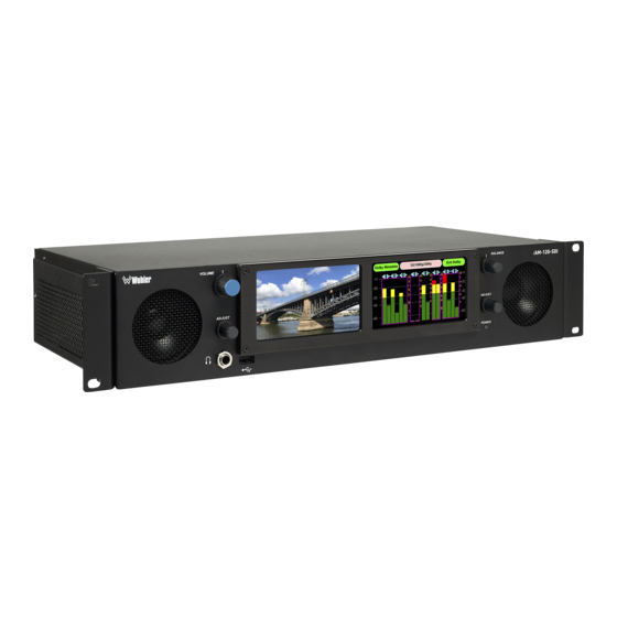
2RU, 4K/12G Multi Channel, Touch Screen Audio/Video Monitor User Guide Part Number 821827, Revision G... - Page 2 In no event will Wohler Technologies, Inc. be liable for direct, indirect, special, incidental, or consequential damages resulting from any defect in the hardware, software, or its documentation, even if advised of the possibility of such damages.
-
Page 3: Table Of Contents
TABLE OF CONTENTS Table of Contents User Guide ..................1 TABLE OF CONTENTS ................3 Table of Contents ................... 3 CHAPTER 1: Installation ............... 7 Introduction ....................7 Overview .................... 7 Safety ......................7 Instructions ..................7 Safety Symbols ..................8 Mounting..................... - Page 4 System Reboot .................. 57 Factory Reset ..................58 System Information ................59 CHAPTER 3: Technical Info ............... 61 CHAPTER 4: The iAM-12G-SDI Web GUI ..........66 Web Browser / Control Device................ 66 First Time IP Assignments ................66 Peer-to-Peer Connection..............66 Network Connection................
- Page 5 Updating via the Web GUI using a Flash Drive ..........114 Updating an iAM-12G-SDI Remotely ..............116 Updating Multiple Units Remotely ..............118 APPENDIX B: Dante Network Setup ............121 Introduction ....................121 What is in the iAM-12G-SDI for Dante ............122 Dante Device Setup ..................123 Dante Clock Selection ..................124 Channel Names...................124 AES67 .......................125...
- Page 6 APPENDIX E: API Documentation ............139 Introduction ....................139 API: Presets ....................139 Page 6...
-
Page 7: Chapter 1: Installation
The iAM-12G-SDI has options for VoIP formats including SMPTE 2022-6, 3G/HD/SD-SDI, and a growing range of additional I/O options via SFP interfaces. Refer to the Specifications section of this manual or contact Wohler Sales for more information. The iAM-12G-SDI is compact and simple to operate. It has touch screen LCD displays providing high resolution meters, menus and basic monitoring controls. -
Page 8: Safety Symbols
5. Do not install near any heat source such as a radiator, heat register, amplifier, or stove. 6. Do not attempt to plug the unit into a two-blade outlet (with only two prongs of equal width). Important: By design, the supplied AC mains power cord will only plug into a three-prong grounded outlet for your safety. -
Page 9: Heat Dissipation
Heat Dissipation The ambient temperature inside the mounting enclosure should not exceed 40° Celsius (104° Fahrenheit). Adjacent devices can be rack mounted (or stacked) in proximity to the unit if this temperature is not exceeded. Otherwise, allow a 1RU (1.75”/44.45mm) space above and below the unit for air circulation. Important Heat generated by the class D power amplifiers, power supplies, and other components is vented by slots in the sides and back of... -
Page 10: Ices-003
provide reasonable protection against harmful interference when the equipment is operated in a commercial environment. This equipment generates, uses, and can radiate radio frequency energy and, if not installed and used in accordance with the instruction manual, may cause harmful interference to radio communications. Operation of this equipment in a residential area is likely to cause harmful interference, in which case the user will be required to correct the interference at their own expense. -
Page 11: Chapter 2: Local Operation
CHAPTER 2: Local Operation Startup The iAM-12G-SDI unit will begin its startup process when it is connected to power. There is no power switch. It is normal for the product to require about a minute to start up and be ready to use. - Page 12 8. USB 2.0 Port: This USB Type A connector allows you to use a flash drive (not supplied) to perform software updates and copy system configurations to another iAM-12G-SDI or to a PC. Software updates are accomplished from the Web GUI. 9. Level Meters: High resolution bar graph meters appear here showing the levels of up to 16 channels selected for monitoring.
-
Page 13: Rear Panel
Rear Panel The rear panel is shown in Figure 2-2. Figure 2-2: iAM-12G-SDI Rear Panel Layout 1. AC Power IEC Plug: The AC inlet is a standard IEC receptacle for 100 to 240 VAC ±10%, 50/60 Hz power connection. Four regional AC power cords, supplied according to shipping region, are available. - Page 14 3. Network Port: The MGMT Ethernet port can connect to either a LAN or to a PC to let you customize the iAM-12G-SDI configuration remotely. The Wohler Web GUI is described in Chapter 4 of this manual. 4. 12G/3G/HD/SD-SDI Inputs: Two inputs are provided to interface to a range of video signal inputs up to UHD 4K resolution.
- Page 15 The SFP modules are hot swappable for convenience. An optional license key must be purchased to enable each module. A software license must be installed for an SFP port to function. Contact Wohler Technical Service to install software licenses. The following SFP modules are compatible with these inputs: a.
- Page 16 1 - 16. Tascam cables may be used, and can be purchased by contacting Wohler Sales. Refer to Figure 2-4 for the pinout of this pair of connectors. The Balanced Analog DB-25 Outputs are standard on the iAM-12G- SDI.
- Page 17 When these outputs are used to connect to an external amplifier and Note: speakers, the external amplifier should be muted whenever the iAM-12G-SDI is being powered up or powered down. Figure 2-5: Analog XLR Output Connections...
- Page 18 MADI BNC: This COAX input accepts an AES10 64-channel signal at a 48 kHz sample rate. The COAX output is reclocked from the MADI source. When power to the iAM-12G-SDI is not present, the COAX input and output are automatically connected together to allow the MADI signal to pass through.
-
Page 19: Sfp-2022-6 / Sfp-2110 Address Setup
Figure 2-7: SFP-2022-6 and SFP2110 Network Diagram The optional SFP-2022-6 or SFP-2110 module furnished by Wohler Technologies is manufactured by Embrionix and comes from the factory with a default IP address. To integrate it into your digital network, you need to set its address to the source to be monitored. -
Page 20: Channel Meters And Touch Operations
Audio meters are displayed on the touchscreen display in labeled clusters, as shown in Figure 2-8. The clusters of channels and other options relating to this are defined using the iAM-12G-SDI Web GUI software as described in Chapter 4. Figure 2-8: Audio Level Meter Screen 1. - Page 21 If these symbols appear on a channel pair, they indicate that this channel pair is a Dolby bitstream, but that the Dolby Decoder within the iAM-12G-SDI is still booting up and that you may not yet select the Dolby Zoom function on them. The Dolby Decoder takes about 90 seconds to boot up when the system is first powered.
- Page 22 The following describes each function: a. Mute / Un-Mute Selection: A violet box surrounds any channel cluster that is muted. Typically, when the iAM-12G-SDI is first powered, all of the channel clusters are muted. Touching a muted channel cluster un-mutes it and removes the violet box.
- Page 23 Back Surround Right After adjusting the Channel Routing, press the Adjust B control again or touch anywhere on the meters to save the change and resume monitoring the combination of monitored clusters as before you soloed the channel. 6. Phase Indicators: There is one Phase Indicator per channel pair. It is pale green when the channels are in phase and bright red when they are out of phase.
-
Page 24: Dolby Monitoring Screens
Dolby Zoom screen. Dolby D, DD+, and E decoding is an optional feature requiring either the OPT-DOLBY the OPT-DOLBY ATMOS module. Contact Wohler Technical Service to install software licenses. - Page 25 defined above. Figure 2-9 shows an example of Integrated Level Gated loudness. Examples of other loudness measurements are shown in Figures 2-10, 2-11, and 2- 12. The loudness measurements that may be shown are: 1. Integ. Level Gated Loudness: Loudness measurement is integrated over a period, but gated by speech levels exceeding a certain level.
- Page 26 Figure 2-11: Short Term 10s Ungated Loudness Figure 2-12: Momentary To reset the loudness calculations, press and hold the Adjust A knob for 3 seconds until the red Resetting Loudness appears over the loudness measurement. Note that above the channel meters are designations for each channel. These designations vary depending upon the Dolby speaker configuration.
- Page 27 Table 2-2: Speaker Configuration versus Channel Labels Speaker Channel Config. C Lfe Ls Rs C Lfe Ls Rs Lrs Rrs 5.1.2 C Lfe Ls Rs Ltm Rtm 5.1.4 C Lfe Ls Rs Ltf Rtf Ltr Rtr 7.1.2 C Lfe Ls Rs Lrs Rrs Ltm Rtm 7.1.4 C Lfe Ls Rs Lrs Rrs Ltf Rtf...
- Page 28 Various Presentations in a Dolby ED2 stream may be selected and monitored. The selected Presentation is shown at the bottom center of the screen, as seen in Figure 2-13. Press the Adjust A knob to change between Presentations. Figure 2-13: Dolby ED2 Presentations Various Programs in a Generic Dolby E stream may be selected and monitored.
-
Page 29: Dolby Metadata
It will vary according to the type of Dolby signal. For example, for checking Guard Band, the iAM-12G-SDI will display the Line Position of each Dolby E bitstream of the Dolby signal. For Dolby ED2, two line positions will be displayed. - Page 30 Figure 2-16: Dolby MetaData Screen Loudness Tab Touching the Presentation Data tab on the Dolby MetaData Screen will show data related to the audio bed and dynamic objects displayed on the Visualizer Screen. The audio bed is the arrangement of speakers in the listening room. The sounds produced by the audio bed accurately simulate the locations of the dynamic objects, which are heard as sound sources from any location in the listening room.
-
Page 31: Dolby Ed2 Stream Selection And Decoding
Dolby stream, you must select the first (leftmost) of the two streams in order to zoom into it. This is because the iAM-12G-SDI is not able to detect the start pair automatically. So in the case shown in Figure 2-18, you would select the stream indication on channel pair 7-8 for a Dolby Zoom. -
Page 32: Dolby Preset Monitoring Screen
Figure 2-19, at the center top of the screen. Figure 2-19: Dolby Preset Monitoring Screen If a Dolby Preset was selected as the iAM-12G-SDI is powered down, it Note: will then reappear when the iAM-12G-SDI is powered up again. However, since... -
Page 33: Dolby ® Atmos Visualizer Screen
MetaData, and route the audio externally to SDI or analog outputs on the rear panel. To complement this feature, the iAM-12G-SDI contains a screen which can help you visualize the location of each audio bed or dynamic channel, both actual and dynamic channels. - Page 34 Figure 2.22 – Dolby ATMOS Visualizer Screen Front View Front View: English Dialogs Figure 2-22 shows the listening room with a 3D front view, with a representation of the video program screen location shown in the center as a white rectangle. The various objects are shown as named audio bed objects (in blue boxes) or as numbered dynamic objects (in green circles).
-
Page 35: Menu / Option Touchscreen
By far, most of the option settings are performed using the Web-based GUI software. However, there are a few commonly used setting and information screens that are available locally in the iAM-12G-SDI using the Menu which appears on the left screen. Figure 2-24 is a diagram of the menu arrangement, a tree showing how to reach any screen or menu from the Menu. -
Page 36: Menu
Menu To access the submenus, touch one of the selector buttons presented on the screen, as shown in Figure 2-25. To return to the Audio Meters display, touch the Audio Meter selector button. Figure 2-25: Menu The function of each of these selector buttons is described in the following sections. Audio Meters Touch the Audio Meters button in the Menu to switch to the main audio metering screen. -
Page 37: Source Select
1. The most recently selected source is shown in light blue. 2. Sources that the iAM-12G-SDI is equipped to monitor are shown in blue. 3. Sources that the iAM-12G-SDI is capable of monitoring, but are not licensed for monitoring are shown in gray. If you would like to license additional signals, contact Wohler to purchase the source module and/or license. -
Page 38: Presets
Figure 2-27: Channel Select Screens: AoIP Back Menu AoIP CH 1-16 AoIP CH 17-32 AoIP CH 33-48 AoIP CH 49-64 MADI BNC MADI Optical Back Back Menu Menu MADI CH 1-16 MADI CH 17-32 MADI CH 1-16 MADI CH 17-32 MADI CH 33-48 MADI CH 49-64 MADI CH 33-48... -
Page 39: Preset Favorites
Preset Favorites Touch the Preset Favorites button to display the Preset Favorites screen. This shows the Presets that you have designated as Favorites. Refer to the Dashboard section of Chapter 4. Generally, these are frequently used Presets that you want to separate out from the possibly many other Presets in the system. -
Page 40: All Presets
All Presets Touch the All Presets button to display the All Presets Group Selection screen as shown in Figure 2-30. If no Presets have been created, the screen in Figure 2-32 appears instead. Figure 2-30: All Presets Screen – Group Selection Menu Active Preset: Operator 1 / Comedy Operator 1... -
Page 41: Loudness Meter
Figure 2-32: All Presets Screen – No Presets Preset Favorites Menu No presets have been created. You can use source select Create presets using the iAM-12G web interface. To return to the Menu from this screen, touch the Menu button. Loudness Meter Touch the Loudness Meter button to reach the Loudness Meter Screen. - Page 42 The Program Loudness (shown as -22.5 LKFS in the figure above) is shown digitally at the upper left of the screen as well as on the meter in the center. At the base of the meter in the center, one of three indications appears: 1.
-
Page 43: Loudness Settings
Audio Meters screen. Loudness Settings Touch the Loudness Settings button to display the Loudness Settings screen. This screen allows you to change between Manual and Continuous Monitoring Modes, and also to set the Alarm mode. It also provides a summary of various Loudness settings, as set in the Configuration | System Preference | Loudness Configuration tab of the Web GUI. -
Page 44: System Options
Web GUI Loudness Settings: These settings are included on this screen for reference only. They cannot be changed on this screen. 1. Standard: This is the loudness standard by which the loudness calculation is made. 2. Reference: This is the set point in the loudness measurement about which the determination is made as to whether an alarm should be displayed. -
Page 45: Dolby Settings
4. Atmos Decode: This setting applies Dolby Digital Plus and ED2 (ED2: Dolby E + Evolution) bitstreams only. (If the optional Dolby Atmos license is not contained in the iAM-12G-SDI, then this option will always be set to the Off position. Contact Wohler Sales to obtain this license.) Set the Dolby Atmos... - Page 46 Decode touch switch to On to enable Dolby Atmos content decoding. Set the touch switch to Off to disable Dolby Atmos content decoding. Dolby Digital Plus with Dolby Atmos content is then decoded as Dolby Digital Plus. When Atmos Decode is set to Off, then on the Dolby MetaData screen the Atmos 3D or Show Video buttons do not display.
- Page 47 Compression Cut and Boost controls cannot be adjusted and the screen appears as shown in Figure 2.38. Figure 2-38: Dolby Settings: DD+ Tab, None or RF Mode Dolby Settings Save Cancel Decoder Loudness Compression Mode None Line < > DRC Compression Cut <...
- Page 48 Dolby Settings Screen: Loudness Tab Figure 2-40 shows the option settings on the Loudness tab. Figure 2-40: Dolby Settings: Loudness Tab Dolby Settings Save Cancel Decoder Loudness < > Loudness Standard ATSC Dialogue Intelligence < > Speech Threshold Metering Mode ITU-R BS.1770-4 1.
-
Page 49: Network Settings
Network Settings Touch the Network Settings button in the System Options Menu to display the Network Settings menu as shown in Figure 2-41. This screen lets you view or change the product IP, the Net Mask, and the Gateway. It also lets you switch between a static (fixed) or a dynamic (DHCP) network address. - Page 50 cancel the address change operation and return to the Network Settings screen. 3. When the address is typed, touch the Enter button. This will return to the Network Settings screen and the changed address can be seen. To change from a static (fixed) to a dynamic (DHCP) network address, touch the DHCP button.
-
Page 51: Output Configuration
Output Configuration screen. Contained in this menu is an Analog Output Reference as illustrated in Figure 2-44. The parameters set on this tab pertain to the DB25 and XLR connectors on the rear panel of the iAM-12G-SDI. Figure 2-44: Analog Output Reference There is only one setting on the Analog Output Reference tab: 1. -
Page 52: Speaker Options
Touching the Speaker Options button on the System Options Menu displays the Speaker Options screen as shown in Figure 2-45. The controls on this screen affect various characteristics of the monitored audio as heard on the iAM-12G-SDI. Figure 2-45: Speaker Options... -
Page 53: Meter Scales
Meter Scales Touching the Meter Scales button on the System Options Menu displays the Meter Scales screen as shown in Figure 2-46. The controls on this screen select the scale standards as well as the ballistics that will be applied to the audio meters. Figure 2-46: Meter Scales Screen The controls function as follows: 1. - Page 54 Table 2–4: Meter Limits and References Default Color Default Ballistics Default Bounds Scale Bottom Limit Top Limit Reference Lower Upper Float -72 Dbfs 0.0 Dbfs 0 Dbfs = 0 Dbfs -30 Dbfs -20 Dbfs Type I VU -13.25 dBr +13.0 dBr -18 Dbfs = 0 dBr 0 dBr 8 dBr...
-
Page 55: App Settings
There is one setting: 1. Enable Logs On USB: When this setting is turned On, records of internal actions and events within the iAM-12G-SDI are recorded onto a flash drive inserted into the USB connection on the front panel. This feature would generally be used under advice from Wohler Technical Service. -
Page 56: System Software Update
Software Version 1.5.21 Wohler iAM12G Monitor 1.5.21 If you have any doubt as to whether you should press Yes, press Back instead, and contact Wohler Technical Service for advice. Pressing Back will return you to the System Options menu. Page 56... -
Page 57: System Reboot
Figure 2-50: System Reboot If you have any doubt as to whether you should press Yes, press Back or No instead, and contact Wohler Technical Service for advice. Pressing Back or No will return you to the System Options menu. -
Page 58: Factory Reset
Mac address 28.) If you have any doubt as to whether you should press Yes, press Back or No instead, and contact Wohler Technical Service for advice. Pressing Back or No will return you to the System Options menu. -
Page 59: System Information
System Information Touching the System Information button in the Menu displays the System Information screen as shown in Figure 2-52. This is a tabbed screen that will let you view various system data, as well as data for any options that are part of the system. - Page 60 Figure 2-54: System Information Screen – 919464 Tab Figure 2-55: System Information Screen – 919475 Tab System Information Menu System 919469 919464 919475 Type AoIPOption State Valid Version 1.7.33 Hardware Revision Upgraded for Revision Page 60...
-
Page 61: Chapter 3: Technical Info
CHAPTER 3: Technical Info Table 3–1: iAM-12G-SDI Specifications Specification Values/Domains Power Requirements 100 VAC to 240 V AC ± 10%, 50/60Hz Power Consumption 40 Watts Dimensions (2RU) 3.5” x 19” x 9.5” (88mm x 483mm x 242mm), (H x W x D) standard 19”... - Page 62 Specification Values/Domains AES Inputs 8 AES channel pairs on HD-15 Ultra HD (4K): 2160p23.98/24/25/29.97/30/50/59.94/60 2K: DCI 23.98p/23.98PsF/24p/24PsF 3G: 1080p50/59.94/60 1080p23.98/24/25/29.97/30/ Video Formats 1080Sf23.98/24/25/29.97/30 1080i50/59.94/60 720p23.98/24/25/29.97/30/50/59.94/60 625i50 PAL 525i59.94 NTSC Dolby ATMOS / E / D / DD+ (E-AC3) Audio Formats Up to 48 kHz audio SDI Input 75Ω...
- Page 63 Table 3–2: iAM-12G-SDI Processing Options Option Part # Description Allows decoding and monitoring of Dolby® D, DD+, E, and ATMOS from SDI, SMPTE OPT-DOLBY 829163 ATMOS 2110, SMPTE 2022-6, and AES streams. Hardware card with software activation key. Allows decoding and monitoring of Dolby®...
- Page 64 (fiber) Connectors. SFP Module with software Fiber activation key. **emSET is configuration software that is necessary so that you can set up this module. It is available at no cost either from its manufacturer, Embrionix, or by contacting Wohler Technologies Technical Service. Page 64...
- Page 65 Figure 3–1: iAM-12G-SDI Block Diagram Touchscreens for Video / 3D Visualizer / Audio Meters / Control SFP Cage for 3G-SDI Output Main Menu Video Optional - or - Output Processor HDMI Output Module 4K Video 12G-SDI Input 1 Two 12G-SDI Inputs...
-
Page 66: Chapter 4: The Iam-12G-Sdi Web Gui
IP address would be 169.254.1.40 (40 is the decimal equivalent for the last octet of Mac address 28.) There two basic types of connections that may be used to connect the iAM-12G-SDI to a web browser, a Peer-to-Peer Connection or a Network Connection. -
Page 67: Network Connection
GUI. Network Connection When connected to a network, the iAM-12G-SDI address will need to be changed to another address in order to be compatible with the address assignments for that particular network. Immediately after the host setup is complete, change the iAM- 12G-SDI's address. -
Page 68: Dashboard
Throughout the Web GUI, pages are a click or two away using the list of selections on the left side. The Dashboard page shows all of the available Preset configurations at a glance. The iAM-12G-SDI allows you to assign Presets to particular groups. In Figure 4-2, although 24 Presets have been defined, only the single Favorite Preset is shown. - Page 69 In Figure 4-3, it can be seen that there are three Presets in the Operator-1 group and only one Preset in the Operator-2 group. The currently selected active Preset for local operation is shown in red. In Figure 4-3, this is the Preset named SDI-AES- Mix.
- Page 70 Figure 4–4: Dashboard Preset Edit The Edit options for a Preset are: 1. Delete: Remove the Preset from the system. Do Not delete the currently active Preset. 2. Rename: Rename the Preset, but keep all of its other characteristics. 3. Make Favorite: Make this Preset a favorite. This can be done for frequently used Presets.
-
Page 71: Preset Management
Presets. Almost any number of Presets can be created, saved, and identified with unique names of your choosing. Using these names, Presets can be recalled immediately from the iAM-12G-SDI front panel. Preset Input Routing The Configuration - Preset Management - Preset Input Routing tab is where the routing of input source signals to the meters and the speakers can be defined in virtually any arrangement. - Page 72 Preset, or create a new Preset from an existing Preset. Refer to Figure 4-7: To create a new Preset, first either select a Group from the pull • down list or type the name of a new Group in the Group Name field provided.
- Page 73 click the Reset button that is adjacent to the Autofill button. 4. System Clock Reference: For reliable operation, it is imperative that an appropriate clock reference selection be made. This is done in a pull down menu. Refer to Figure 4-8. The lack of an appropriate clock reference may result in erratic monitoring or no ability to monitor at all.
- Page 74 Figure 4–9: Cluster Assignment In the Cluster box, you can select the type of Cluster from a pull down selection. The available Cluster Type selections are: Mono 1.0: The channel will appear within a single-channel cluster. • Stereo 2.0: The channels will appear within a two-channel cluster. •...
- Page 75 Figure 4–10: Speaker Assignment 7. Mute/Unmute: A Mute/Unmute control is provided for each channel, although the adjustment will affect all channels in the Cluster. This allows the operator to just see the meters for certain channels and not hear the audio. This is an alternate action control.
-
Page 76: Dolby Presets
Dolby Presets Dolby Presets are useful for customers who want to simultaneously monitor both Dolby decoded channels and other inputs or want to have an auto-zoom to monitor a certain pair that is known to be carrying Dolby encoded audio. Creating a Dolby Preset is in many ways very similar to creating any other Preset. - Page 77 Note: If the Apply Dolby Zoom Meter Screen option is turned on and if Apply Common Dolby Configurations is selected while creating a Dolby preset, the channel clustering shown on the screen follows the Speaker Configuration as set in the Dolby Configuration. Otherwise, the channel clustering shown on the screen follows the speaker configuration selected while creating a Dolby preset.
- Page 78 the Common Dolby configuration of this unit, simply click the Apply Common Dolby Configurations checkbox. The Dolby Settings section of this chapter explains the Common Dolby Configurations. The screen will then appear as is shown in Figure 4-13. You may also replace some of the decoded channels with un-encoded input Note: source channels so that they can all be monitored on the same meter screen.
-
Page 79: Phase Indicators By Preset
Phase Indicators by Preset The Configuration - Preset Management - Phase Indicator tab is where the Phase Indicators can be enabled to show on the Audio Meters screen or whether they shouldn't according to each Preset. Generally speaking, the Phase Indicators should be shown, but if the channels of any pair contain dissimilar material, then the Phase Indicator for that channel pair should be disabled. -
Page 80: Output Routing By Preset
Output Routing by Preset The Output Routing tab allows you to determine exactly which input channels are routed to which outputs. It appears as shown in Figure 4-15. This very flexible capability allows you to route signals according to Preset or as a default for the whole system. -
Page 81: Output Routing
Output Routing The Output Routing feature (OPT-OUTPUT-ROUTING) allows channels to be routed or combined and routed in custom ways to various destination outputs. Output Routing is applied to: 1. Signals monitored using "Input Source select" from the Front Panel, 2. Presets that have been created to apply the Output Routing. Any change to the routing will affect the Presets that have "Apply Output Routing"... -
Page 82: Destination Outputs
Figure 4-16: Global Output Routing Option Destination Source Output Outputs Inputs Options Destination Outputs On the left of the Global Output Routing screen are listed the Destination Outputs. These are the outputs to which any input can be routed. They are as follows: 1. -
Page 83: Source Inputs
SDI output channels 9 through 16 and that is not configurable. Source Inputs The source inputs which may be routed are described in this section. 1. Cluster Information: Cluster information shows the type of cluster and the cluster name. 2. Speaker Assignment: Speaker assignment can be used to configure to which speakers the audio is routed to. -
Page 84: Typical Questions Regarding Output Routing
What signal outputs can be controlled using the Output Routing feature? All the outputs on the iAM-12G-SDI can be controlled using the Output Routing feature. This includes – Internal Speakers, Analog XLR outputs, all 8 pairs of Analog DB25 outputs and 4 pairs of SDI SFP outputs. -
Page 85: How Do I Have A Downmixed Pre-Fade Output On Analog Db-25 Pair-1
checkboxes. As shown in the above example, signals appearing on Audio Meter channels 1 and 2 are routed to the Analog XLR outputs. This output is volume and balance controlled and will follow the Solo/Mutes on the Audio Meter screen. How do I have a downmixed pre-fade output on Analog DB-25 Pair-1 combined with a post-fade output on the Analog XLRs? To control whether a specific output is pre-faded or post-faded use the Volume... -
Page 86: Would I Configure Different Outputs For Source Select Choices
The Global Output Routing feature works great. But what if we don't want to create any Presets and want to monitor audio only using Source Select? How would I configure different outputs for Source Select choices? Use the Global Output Routing settings to determine how the outputs are configured for source select options. -
Page 87: Amplified Stereo Speakers Connected To The Analog Xlr's
How do I ensure that my outputs are pre-faded but follow the solo-mutes? This will allow us to monitor only the unmuted/solo Audio Meter channels on amplified stereo speakers connected to the Analog XLR’s. In the Output Routing setting, for the Analog XLR outputs, keep the Volume Control checkbox unchecked and the Solo/Mute checkbox checked. -
Page 88: Preset Replication
To start Preset Replication, click on the Preset Replication tab on the master unit. This will start the unit discovery process and will list all the iAM-12G-SDI units that you currently have on your network. The discovery process will continue for a period of 2 minutes. - Page 89 Figure 4-18: Preset Replication Target Selection Screen Click either From Master Unit or Select Preset File. This determines the source of the Presets to be copied. Preset Files would be files that you have previously stored in the computer running the Web GUI. You may add a descriptive name or version to the Presets being copied.
-
Page 90: Remote Monitor
Remote Monitor Click on the Remote Monitor page to provide a live view of the audio bar graph and Loudness meters for the current preset. There are two tabs, Audio Meters and Dolby Metadata. Audio Meters The following figure shows the Audio Meters tab. Figure 4–19: Remote Monitor Audio Meters The left side of the screen shows the level meters for the currently selected input source. -
Page 91: Dolby Metadata
Dolby Metadata The following figures show various Dolby metadata tabs that might be presented. Figure 4-20 – Remote Monitor ED2: Multiple Presentations Page 91... - Page 92 Figure 4-21 – Remote Monitor ED2: Single Presentation Page 92...
- Page 93 Figure 4-22 – Dolby ED2 Misalignment Information Note: In the figure above, the first substream is the reference and its misalignment value is always 0. Page 93...
- Page 94 Figure 4-23 – Remote Monitor Dolby E / DE Page 94...
- Page 95 Figure 4-24 – Remote Monitor DD+ with ATMOS Page 95...
-
Page 96: System Setup
It is shown in Figure 4-25. Figure 4–25: System Setup: System Information The name of this particular iAM-12G-SDI is shown as the last item in the Unit Information section. It is changeable on this screen by clicking into its field and typing a new name and then click the Apply button. -
Page 97: Sfp Information
SFP Information For certain I/O modules, the System Setup page will also display the Hardware/Vitals status for each module. The examples in Figures 4-26 and 4-27, show the status of the module in SFP Slot 1. The actual information listed in each of these tabs depends upon the module itself, but these figures show some of the types of information and details available. - Page 98 Figure 4–27: System Setup: SFP Information Page 98...
-
Page 99: Licenses
The System Setup | Licenses tab shows the license keys for each of the optional features installed in this iAM-12G-SDI. You may also use this tab to enter new license keys, or enable some license keys. This tab is shown in Figure 4-28. -
Page 100: Configuration: Management Ip Address
Configuration: Management IP Address Make network IP Address changes for Management (MGMT) Port of the local iAM-12G-SDI on the screen shown in Figure 4-29. This screen allows you to configure the management port IP address for the device. Note that after changing the IP address, the web interface should be loaded with the new IP address. -
Page 101: Configuration: System Preferences
Configuration: System Preferences The System Preferences selection contains three tabs, Loudness Configuration, Phase Indicator Configuration, and Dolby Settings. They allow you to customize screens and measurements. They are explained in the following three sections: Loudness Configuration The Loudness Configuration tab is shown in Figure 4-30. Figure 4-30: Loudness Configuration Tab 1. - Page 102 a. Over: The Alarm indication will only appear when Loudness has exceeded the Reference Level by the Tolerance amount. b. Under: The Alarm indication will only appear when the Loudness has been below the Reference Level by the Tolerance amount. c.
-
Page 103: Phase Indicator Configuration
Phase Indicator Configuration The Phase Indicator Configuration tab is as shown in Figure 4-31. It allows you to select which channel pairs by default will receive a phase meter on the Metering Screen. Generally, it is useful to monitor the relative phase of stereo pairs. However, sometimes each channel of a pair is unrelated to each other. -
Page 104: Dolby Settings
ED2 (ED2: Dolby E + Evolution). (If the optional Dolby Atmos license is not contained in the iAM-12G-SDI, then this option will always be set to the Off position. Contact Wohler Sales to obtain this license.) Click the Dolby Atmos Decode switch to On to enable Dolby Atmos content decoding, or set the switch to Off to disable Dolby Atmos content decoding. - Page 105 4. Dolby Surround Upmix: The Dolby Surround Upmix option upmixes channel-based content, but does not apply to audio objects. This setting applies to Dolby Digital Plus bitstreams only. To enable Dolby Surround Upmix, the Dolby Atmos Decode option must be turned On. Set the Dolby Surround Upmix switch to On to enable to enable the Dolby Surround Upmix option.
-
Page 106: Configuration: Import/Export Presets
Likewise, it can be used to import a Preset database from a flash drive or the computer hard drive into the iAM-12G-SDI. In this way, using a USB flash drive, a Preset configuration may be only devised once and then duplicated into all of the iAM-12G-SDI units in a system, saving significant effort. -
Page 107: Import Configuration
2. Select either the USB Flash Drive button or the Hard Drive button. 3. If you have selected the USB Flash Drive button, insert a flash drive in the front panel USB jack on the iAM-12G-SDI you want to recover Preset data from. - Page 108 4. If you want to allow existing Presets to be overwritten with imported Presets of the same name, check the Overwrite an existing Preset box. It is a good idea to do this. 5. Click the Submit button. The copying will proceed. Do not withdraw the flash drive before all of the data is read from it.
-
Page 109: System: Factory Reset
If you have any doubt as to whether you should perform a Factory Reset, do not click the Reset button. Contact Wohler Technical Service for advice. Factory Reset will reset your IP address to the default one (Static IP: Note: 192.168.1.162/Gateway: 192.168.1.1/Netmask: 255.255.255.0) and clear the... -
Page 110: System: Reboot System
Figure 4–37: Reboot System If you have any doubt as to whether you should reboot the remote iAM-12G-SDI, do not click the Reboot System button. Contact Wohler Technical Service for advice. -
Page 111: Appendix A: Software Upgrades
Introduction This chapter describes how to download a software update file to your computer, transfer it to a USB flash drive and install the updated into an iAM-12G-SDI. Download the Software The iAM-12G-SDI software update can be found at http://www.wohler.com, under Product Downloads on the Products >... -
Page 112: Local Update From The Front Panel
USB flash drive. 2. Insert the USB flash drive with iAM-12G-SDI update package(s) into the front panel USB jack. 3. From the Menu screen, touch System Options. The screen shown in Figure A-1 will appear. - Page 113 Note: If you attempt a software upgrade fairly soon after you have powered up the iAM-12G-SDI, and it contains a Dolby Decoder module, it can happen that the Dolby Decoder module hasn't yet had enough time to boot up. In this case, the screen shown in Figure A-5 will appear.
-
Page 114: Updating Via The Web Gui Using A Flash Drive
USB flash drive. 2. Connect to the iAM-12G-SDI with the Wohler Web GUI. Navigate to the System | System Update menu, as shown in Figure A-6. If the iAM-12G-... - Page 115 Figure A-6 – System Update Menu 3. Click on the Refresh button. 4. Available software update(s) are shown as in Figure A-7. Click the one you want, followed by clicking the System Update button. Figure A-7 – Available Software Updates 5.
-
Page 116: Updating An Iam-12G-Sdi Remotely
Use the following steps to update the iAM-12G-SDI software: 1. The Software Update files you downloaded earlier must be in the same computer that is running the Web GUI. Connect to the iAM-12G-SDI with the Wohler Web GUI. Navigate to the System | System Update menu. Click within the large blue dotted line rectangle at the right of the screen. - Page 117 3. At this point, wait for the update to complete. It may take several minutes, until it is critical not to disturb the iAM-12G-SDI or the Web GUI the update process is complete. When it is complete, the iAM-12G-SDI will restart.
-
Page 118: Updating Multiple Units Remotely
Use the following steps to update one or more iAM-12G-SDI units remotely by transferring the software from a previously updated iAM-12G-SDI: 1. If any of the iAM-12G-SDI units that you intend to update remotely may be in use, contact the people using them and let them know what you will be doing. - Page 119 Figure A-14 – List of Found iAM-12G-SDI Units 4. Then click Update Selected Devices. The window shown in Figure A-15 will appear. Figure A-15 – Apply System Package 5. Click Apply System Update. The screen shown in Figure A-16 will appear.
- Page 120 Figure A-16 – System Update Progress 6. At this point, wait for each update to complete. It may take several minutes, it is critical not to disturb any of the iAM-12G-SDI units or the until the update process is complete. When it is complete, each Web GUI iAM-12G-SDI will restart.
-
Page 121: Appendix B: Dante Network Setup
AoIP option is installed. The iAM-12G-SDI is set up at the Wohler factory to be used as a slave rather than a master within the Dante network. Other devices or software, such as a Dante Controller, are expected to be responsible for most device configurations and all audio routing. -
Page 122: What Is In The Iam-12G-Sdi For Dante
AoIP address per DHCP or local link protocols. There is no need to set a static address for the iAM-12G-SDI Dante port, so no address entry method is provided in the iAM-12G-SDI for Dante network setup. While it is possible to Manually Configure an IP Address from the network, this is not a recommended Dante practice and should not be done. -
Page 123: Dante Device Setup
6 digits of the Dante port MAC address, as shown in Figure B-3. This name can be changed by the Dante Controller to appear that way on the network, but that will not change the iAM-12G-SDI’s unit name appearing on GUI pages and iAM- 12G-SDI Remote Metering or Discovery pages. -
Page 124: Dante Clock Selection
Dante Clock Selection While the Brooklyn’s internal clock is highly accurate, the iAM-12G-SDI does not have provisions for external sync clocks, such as those that are GPS or media reference (video genlock or audio word clock) based. So it is generally not the best candidate to be the PTP Master Clock (commonly called the “grandfather clock”) for... -
Page 125: Aes67
AES67 The iAM-12G-SDI Brooklyn II can be configured for AES67 operation. AES67 operation with Dante is limited to eight or less receive and transmit channels at 48 kHz sample rates. 24 bit linear (L24) encoding and 1 msec packet time are fixed default transmit parameters. -
Page 126: Device Lock
Flows window shown in Figure B-8. Figure B–8: Multicast Device Lock Audinate recently added a feature whereby a remote controller can send a command to lock Dante network device configurations. The iAM-12G-SDI does not implement the Device Lock command at this time. Page 126... -
Page 127: Dante Firmware Upgrades
Dante Firmware Upgrades Wohler iAM-12G-SDI monitors ship with current Brooklyn II firmware as of the option installation date. The version information is found in the Dante Controller Device View-Status page. iAM software/firmware is tested with the latest Dante code release. Therefore it is strongly recommended that iAM-12G-SDI and Dante software/ firmware be updated at the same time to ensure compatibility and support of the latest features. -
Page 128: Appendix D: Ravenna (Zman) Setup
APPENDIX D: Ravenna (ZMAN) Setup Introduction Installing the iAM-12G-SDI into an existing and functioning Ravenna network using the Merging ZMAN Card is virtually plug and play. The iAM rear panel AoIP jack supports 1Gb/s and 100Mb/s Ethernet devices in Ravenna Audio over IP network configurations. -
Page 129: Configuring The Aoip Merging Option Card
The Merging Ravenna card runs specific firmware from Merging and augmented by Wohler for use within the iAM-12G-SDI. The card will not function correctly if the user downloads and installs firmware from any source besides Wohler. The Wohler augmentation includes the ability to support 64 channels. -
Page 130: Getting Started | General Settings
item View is enabled. Do not proceed until the card shows on Aneman. Right click on that line and select Web Services: Advanced (or Ravenna) to bring up the Merging Ravenna configuration page. Also, the ICON of the card will appear in the main part of the Aneman screen. -
Page 131: Getting Started | Ptp
Getting Started | PTP This tab is shown in the following figure. This configuration page refers to how your Ravenna network is synchronized to clocks. Figure D-2: Getting Started | PTP The elements of this tab are as follows: 1. Global Settings: The default value for PTP a. -
Page 132: Getting Started | Session Sources
3. Status: a. Lock: This shows if the device is locked to PTP (Locked -Locking - Unlocked) b. Master: This is true or false for the current device. c. GMID: This is the current GrandMasterID (PTP Master) d. Delta (ns): This is the time delta between the device and the PTP master. -
Page 133: Getting Started | Session Sinks
8. Payload type: RTP Payload type - This value should not be modified. 9. Codec: The possible bit rate values are L24, L16, DSD64, DSD64_32, DSD128, DSD128_32, and DSD256. Note that these values are sampling rate dependent. 10.Frame size (samples): This the frame size of the current source. 11.DSCP: The audio DSCP should be set to 34 for RTP AES67 or 46 for RTP Ravenna. -
Page 134: Getting Started | Session Info
5. Manual: This allows manual entry of an SDP. 6. Delay (samples): This sets the playback delay. 0 is automatic delay. 7. Ignore RefClk GMID - accept source locked to any PTP master: This feature is useful when you want to connect a stream through Internet (for example with two PTP Masters (GPS) at each location. -
Page 135: Getting Started | Ins/Outs
Getting Started | Ins/Outs This tab allows you to change the name of the specific Inputs and/or Outputs. Figure D-5: Getting Started | Ins/Outs Getting Started | I/O Router This page allows remapping of incoming channels to different internal channel assignments. -
Page 136: Operation
IAM interface for display on meters and speakers, etc. The iAM-12G-SDI must be set to receive AOIP from the Source Select Front Panel menu or a browser iAM-12G-SDI GUI. - Page 137 For example, for monitoring 2 SDI sources (four 8 channel Flows), assign two flows to 1-8 and 9-16 and the next SDI signal to 17-24 and 25- 32. Touch the iAM-12G-SDI AOIP selection menu to select the proper range to monitor, up to 57-64.
-
Page 138: Zman Session Sources
Figure D-8: Session Sources Tab ZMAN Updating The Zman card is pre-initialized with the correct Wohler firmware load. In case of future upgrades, use the following steps: 1. In Aneman, right click the ZMAN entry on the bottom Devices section, and select Maintenance Mode. - Page 139 Follow the instructions in the First Time IP Assignments section of Chapter 4 to achieve the required network connection. API: Presets 1. GET Active Preset Method: GET /api/cf/presets/current Example Response: "serial_number": "", "model": "iAM-12G-SDI", "version": 1.3, "name": "iAM-12G-SDI", "result": { "group": { "Id": 1, "Name": ""...
- Page 140 "error": null, "params": { "PresetId": "result": { "GroupId": 1, "PresetName": "SDI", "Data": { "Name": { "Program": "", "Group": "G1", "Preset": "SDI" "VideoSource": { "InputNo": 1, "ConnectorType": "BNC", "Slot": 1, "Type": "SDI", "Cage": "DolbyDetection": { "NonAudio": "Enabled", "PaHeader": "Enabled" "Clusters": [ "NumberOfMeters": 2, "FirstMeter": 1, "Name":...
- Page 141 "MuteOnPresetRecall": true "NumberOfMeters": 2, "FirstMeter": 11, "Name": "Stereo 2.0 #6", "Type": "Stereo", "MuteOnPresetRecall": true "NumberOfMeters": 2, "FirstMeter": 13, "Name": "Stereo 2.0 #7", "Type": "Stereo", "MuteOnPresetRecall": true "NumberOfMeters": 2, "FirstMeter": 15, "Name": "Stereo 2.0 #8", "Type": "Stereo", "MuteOnPresetRecall": true "MeterSet": { "13": { "Source": { "Slot": 1,...
- Page 142 "ConnectorType": "BNC", "InputNo": 1, "InputIndex": 0, "Type": "SDI" "VolumeDb": 0, "DelayMs": 0, "Speaker": "Right" "3": { "Source": { "Slot": 1, "Cage": 1, "Channel": 3, "ConnectorType": "BNC", "InputNo": 1, "InputIndex": 0, "Type": "SDI" "VolumeDb": 0, "DelayMs": 0, "Speaker": "Left" "4": { "Source": { "Slot": 1, "Cage": 1,...
- Page 143 "InputIndex": 0, "Type": "SDI" "VolumeDb": 0, "DelayMs": 0, "Speaker": "Left" "15": { "Source": { "Slot": 1, "Cage": 1, "Channel": 15, "ConnectorType": "BNC", "InputNo": 1, "InputIndex": 0, "Type": "SDI" "VolumeDb": 0, "DelayMs": 0, "Speaker": "Left" "5": { "Slot": 0, "Cage": 0, "ConnectorType": "None", "Source": { "Slot": 1,...
- Page 144 "InputNo": 1, "InputIndex": 0, "Type": "SDI" "VolumeDb": 0, "DelayMs": 0, "Speaker": "Right" "6": { "Source": { "Slot": 1, "Cage": 1, "Channel": 6, "ConnectorType": "BNC", "InputNo": 1, "InputIndex": 0, "Type": "SDI" "VolumeDb": 0, "DelayMs": 0, "Speaker": "Right" "7": { "Source": { "Slot": 1, "Cage": 1, "Channel": 7,...
- Page 145 "Type": "SDI" "VolumeDb": 0, "DelayMs": 0, "Speaker": "Right" "1": { "Source": { "Slot": 1, "Cage": 1, "Channel": 1, "ConnectorType": "BNC", "InputNo": 1, "InputIndex": 0, "Type": "SDI" "VolumeDb": 0, "DelayMs": 0, "Speaker": "Left" "SystemClockSource": { "Slot": 0, "Cage": 0, "ConnectorType": "None", "InputNo": 0, "Type": "None", "Pair":...
- Page 146 "Favorite": 0, "Name": "SDI", "Id": "Id": "Name": "AES", "Presets": [ "Favorite": 0, "Name": "dfsdf", "Id": "Id": 4. GET to recall the preset Method: GET /api/cf/presets/<int:presetID>/activate Example Response: "error": null, "params": { "PresetId": "result": { "PresetId": 1, "GroupId": 1, "PresetName": "SDI", "GroupName": "G1"...
- Page 147 "GroupId": "result": { "GroupId": 6. POST to delete the preset Method: POST api/op/preset/<int:presetID>/delete Example Response: "error": null, "params": { "PresetId": "result": { "PresetId": 7. POST to rename group Method: POST /api/op/group/<int:groupID>/newGrpNameSdi/rename Example Response: "error": null, "params": { "GroupId": 1, "GroupName": "newGrpNameSdi"...
- Page 148 8. POST to rename preset Method: POST /api/op/preset/<int:presetID>/newPresetNameTest/rename Example Response: "error": null, "params": { "PresetId": 1, "PresetName": "newPresetNameTest" "result": { "PresetId": 1, "PresetName": "newPresetNameTest" 9. POST to set preset as Favorite Method: POST /api/op/preset/<int:presetID>/<favoriteVal>/favorite Example Response: "error": null, "params": { "PresetId": 4, "Favorite": "result": {...
- Page 149 "SourceType": <String: SDI Input Source> Note: Allowed SDI input sources are: "Bnc-1.Sdi", "Bnc-2.Sdi", "Sfp-1.Sdi", "Sfp-2.Sdi", "Sfp-3.Sdi", "Sfp-4.Sdi", "Sfp-1.Smpte2022", "Sfp-2. Smpte2022", "Sfp-3.Smpte2022", "Sfp-4. Smpte2022", "Sfp-1. Smpte2110" "Sfp-2. Smpte2110" "Sfp-3. Smpte2110" "Sfp-4. Smpte2110" 2. Body content for MADI "SourceType": <String: MADI Input Source>, "ChannelGroup": <Int: 1-4>...
- Page 150 5. Body content for Aoip "SourceType": "Aoip", "ChannelGroup": <Int: 1-16> Note: ChannelGroup 1 => Channels 1-16 and ChannelGroup 2 => Channels 17-32 and so on 6. Body content for TOSLINK "SourceType": "TOSLINK" 11. Setting Mute/Unmute Clusters Method: PATCH /api/op/presets/<int:preset id>/mute-clusters "clusters": [ {"name": "MADI 1", "mute": "N"}, {"name": "MADI 2", "mute": "N"},...
- Page 151 "channel_number":1 Page 151...
Need help?
Do you have a question about the iAM-12G-SDI and is the answer not in the manual?
Questions and answers