Table of Contents
Advertisement
Quick Links
Advertisement
Table of Contents

Related Manuals for Wohler iAM1-8


Summary of Contents for Wohler iAM1-8
-
Page 1: User Guide
1RU Multi-Channel Audio Monitor User Guide Part Number 821833, Revision D... - Page 2 In no event will Wohler Technologies, Inc. be liable for direct, indirect, special, incidental, or consequential damages resulting from any defect in the hardware, software, or its documentation, even if advised of the possibility of such damages.
-
Page 3: Table Of Contents
Loudness Settings ................25 Source Select ..................27 Presets ..................... 29 All Presets ..................29 Preset Favorites ................. 31 Unit Settings ..................32 Speaker Options................. 33 Meter Scales..................34 Unit Configuration ................36 Phase Configuration................37 Analog Configuration ................38 Page 3 iAM1-8... - Page 4 System Information ................44 Passcode Settings ................45 Forgotten Passcode ................47 CHAPTER 3: Technical Info ............... 48 CHAPTER 4: The iAM1-8 Web GUI ............53 Web Browser / Control Device................ 53 First Time IP Assignments ................53 Peer-to-Peer Connection..............53 Network Connection................
- Page 5 Updating an iAM1-8 Remotely ................ 94 Updating Multiple Units Remotely ..............96 APPENDIX B: Dante Network Setup ............. 99 Introduction ....................99 What is in the iAM1-8 for Dante? ..............99 Dante Device Setup ..................101 Dante Clock Selection ..................102 Channel Names...................102 AES67 .......................103...
- Page 6 APPENDIX E: API Documentation ............118 Introduction ....................118 API: Presets ....................118 APPENDIX F: Out of Band Control............131 Introduction ....................131 SFP IP Address Configuration ................131 SFP System Configuration ................132 SFP 2110 Configuration................133 SFP 2110 Preset Config ................136 Diagnostic Information.................137 Page 6 iAM1-8...
-
Page 7: Chapter 1: Installation
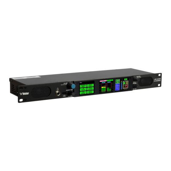
(or channel pairs) from any audio/video source stream may be monitored. The iAM1-8 includes two 3G SDI inputs and it can monitor up to 8 channels of audio from them. Optional modules will allow decoding of an additional SDI input, MADI, AES3, Dolby D, DD+, E, SMPTE 2110, SMPTE 2022-6, and AES streams. -
Page 8: Safety Symbols
Heat generated by the class D power amplifiers, power supplies, and other components is vented by slots in the sides and back of the unit. Therefore, as a safety precaution, you must allow proper ventilation on these surfaces. Page 8 iAM1-8... -
Page 9: Sympathetic Vibration
ICES-003 This Class A digital apparatus complies with Canadian ICES-003. Cet appareil numérique de la classe A est conforme à la norme NMB-003 du Canada. Page 9 iAM1-8... -
Page 10: Chapter 2: Local Operation
Chapter 4 of this manual. The API commands are described in Appendix E of this manual. Startup The iAM1-8 will begin its startup process when it is connected to power. There is no power switch. It is normal for the product to require about 45 seconds to start up and be ready to use. - Page 11 Output Routing option is installed, speaker audio may optionally be set to not mute, using the Wohler Web GUI. Refer to the Output Options section of Chapter 4. If the speaker audio is set to mute with headphone insertion, and a headphone is...
-
Page 12: Rear Panel
Chapter 4 of this manual. Third party equipment, connecting to the iAM1-8 via a LAN plugged into this port and using an API commands, can view and change product options, as well. This API is described in Appendix E of this manual. - Page 13 48 kHz sample rate. An optional license key must be purchased to enable this function. The COAX output is reclocked from the MADI source. When power to the iAM1-8 is not present, the COAX input and output are automatically connected together to allow the MADI signal to pass through.
- Page 14 Technologies Technical Service. e. SMTPE 2110 or 2022-6 Receiver: This uses Multi-Mode 850 NM, LC fiber connectors. It allows the iAM1-8 to monitor SDI audio transmitted in real time over Ethernet. You must use the MN-Set configuration software to set up this option. It is available from Wohler Technologies Technical Service.
- Page 15 Option card. The source of these signals is the monitored audio channels as shown on meters 1 - 8. Tascam cables may be used, and can be purchased by contacting Wohler Sales. Refer to Figure 2-6 for the pinout of this connector.
- Page 16 Ethernet characteristics. However, the two different ports cannot be used simultaneously. You must choose to connect either one or the other. Page 16 iAM1-8...
-
Page 17: Sfp-2022-6 / Sfp-2110 Address Setup
To integrate it into your digital network, you need to set its address to the source to be monitored. You must use the MN-Set configuration software to set up this option. It is available from Wohler Technologies Technical Service. The procedure to accomplish this is described in the SFP-2022-6 / SFP-2110 Setup Guide (part number 821822), which is available at https://wohler.com/downloads/... -
Page 18: Channel Meters And Touch Operations
Cluster. It can also be touched to change which Cluster is being measured. To do this, touch the green Loudness Reading control. It will temporarily turn orange. You may then touch the meters in any other cluster. The Loudness Cluster Marker will then move to that cluster and Page 18 iAM1-8... - Page 19 Mute / Un-Mute Selection: A violet box surrounds any channel pair that is muted. Typically, when the iAM1-8 is first powered, all of the channel pairs are muted. Touching a muted channel pair un- mutes it and removes the violet box. Muting and un-muting by touching is an alternate action function.
-
Page 20: Dolby Zoom Screen
Set which Phase Indicators appear using the Phase Config Menu or with the System Preferences: Phase Indicator Configuration tab in the Wohler Web GUI. Dolby Zoom Screen Dolby Zoom is a very powerful analysis tool. Much as a camera lens can "zoom"... - Page 21 It will vary according to the type of Dolby signal. For example, for checking Guard Band, the iAM1-8 will display the Line Position of each Dolby E bitstream in the Dolby signal. Touching the Exit Dolby button returns you to the monitoring screen from which you came.
-
Page 22: Menu / Option Touchscreen
Analog Config Analog Config Screen Network Settings System Options Screen Network Settings System Reboot System Reboot Screen System Update System Update Factory Reset Screen System Details Factory Reset Screen Passcode Settings System Details Screen Passcode Settings Screen Page 22 iAM1-8... -
Page 23: Main Menu
Loudness Measurement. It is displayed along with the channel meter screens and is shown in Figure 2-13. As shown in Figure 2-13, the Source knob is positioned to the lower left of the Loudness Meter Screen. If the Source Knob Select setting in the Unit Config Page 23 iAM1-8... - Page 24 1. The Loudness RAnge (LRA) is the measure of variation between the calculated loudest and softest passage over the program period (shown as LRA -0.1 above). 2. The Average Loudness is the average of all calculated loudness measurements made over the Program period (shown as PROG - 20.5 Page 24 iAM1-8...
-
Page 25: Loudness Settings
Continuous Monitoring Modes, and also to set the Alarm mode. It also provides a summary of various Loudness settings, as set in the Configuration | System Preference | Loudness Configuration tab of the Web GUI. Refer to Figure 2-14. Page 25 iAM1-8... - Page 26 3. LRA Window: This is a moving window of time over which the loudness measurement is made. 4. Window: This may be set to Momentary, Short, or one of 22 values, ranging from one second to two hours. Page 26 iAM1-8...
-
Page 27: Source Select
This screen also shows sources which are unlicensed and therefore nonfunctional. These sources are shown in a gray color. To license these sources so that they may be used, contact Wohler Technologies. Figure 2-15 shows the Source Select Menu. - Page 28 Menu Back Analog Valid license is required DB25 This selection requires a license from Wohler to enable. Please call at +1-510-870-0810 or email at support@wohler.com. Thank you! Back Touch Back to return to the Source Select menu or touch Menu to return to the Main Menu.
-
Page 29: Presets
Figure 2-17: All Presets Screen - Group Selection The Presets are normally arranged into Groups. Use this screen to select which Preset-containing Group to examine. After selecting one of the Groups, the Preset Selection screen shown in Figure 2-18 is shown. Page 29 iAM1-8... - Page 30 To return to the All Presets Group Selection screen instead, touch the Groups button. To return to the Menu without making a selection, touch the Menu button. Figure 2-19: All Presets Screen - No Presets To return to the Menu from this screen, touch the Menu button. Page 30 iAM1-8...
-
Page 31: Preset Favorites
Preset to select it. To exit this screen without making a selection, touch Menu. If no Favorite Presets have been designated, this screen will appear as shown in Figure 2-21. Figure 2-21: Preset Favorites Screen - No Favorites Page 31 iAM1-8... -
Page 32: Unit Settings
Touching the Unit Settings selection on the Main Menu screen proceeds to the Unit Settings Menu, which contains additional menu selections. The Unit Settings Menu is shown in Figure 2-22. This is an intermediary menu which leads to other menus and screens. Figure 2-22: Unit Settings Menu Page 32 iAM1-8... -
Page 33: Speaker Options
Touching the Speaker Options selection on the Unit Settings Menu screen proceeds to the Speaker Options screen. The controls on this screen affect various characteristics of the monitored audio as heard on the iAM1-8. This screen is shown in Figure 2-23. -
Page 34: Meter Scales
Touch the left or right arrows to select the scale. A representation of the chosen scale will be shown at the right. The possible scales that can be selected are shown in Figure 2-25. Figure 2-25: Meter Scale Selection Page 34 iAM1-8... - Page 35 10 ms to reach -2 dB of IEC Type II -24 dB 2.8 sec. settled reading None Bar or Floating Segment Not Displayed When you have made your choices, touch Save to retain them. Touch Back or Meters to exit this screen. Page 35 iAM1-8...
-
Page 36: Unit Configuration
2. AES termination: AES signals should have one and only one termination. This termination should physically be at the last destination of an AES coax cable. If the iAM1-8 is the last connection in a series of AES connections, then its terminations should be turned on. A symptom of too many terminations (or no termination) is that no signal appears to be present on the AES input. -
Page 37: Phase Configuration
Unit Settings menu. 3. Save & Exit: When you have finished making the changes you want on this screen, touch the Save & Exit button to save the changes and return to the Unit Settings menu. Page 37 iAM1-8... -
Page 38: Analog Configuration
-18 dBFS = +4 dBu g. -18 dBFS = 0 dBu h. -20 dBFS = +4 dBu Touching Save will save any changes made, or touching Cancel will return you to the System Options menu without saving. Page 38 iAM1-8... -
Page 39: System Options Menu
(fixed) or a dynamic (DHCP) network address. Figure 2-30: Network Settings Screen 1. To change the IP Address, Net Mask, Gateway, or DNS, tap the item you would like to change. A keypad will appear, as shown in Figure 2-31. Page 39 iAM1-8... - Page 40 (fixed) network address, touch the DHCP button again. The colors of the buttons will return to the ones depicted in Figure 2-30. Figure 2-32: Network Settings: DHCP 1. To complete the network addressing scheme change, touch the Save button. Page 40 iAM1-8...
-
Page 41: System Reboot
You wish to Reboot the System? If you have any doubt as to whether you should press Yes, press Back or No instead, and contact Wohler Technical Service for advice. Pressing Back or No will return you to the System Options menu. Page 41... -
Page 42: System Update
System Update screen as shown in Figure 2-34, showing the current software version of the product. To update the system software locally from the iAM1-8 front panel, follow the procedure in the Local Update from the Front Panel section of Appendix A. -
Page 43: Factory Reset
Mac address 28.) If you have any doubt as to whether you should press Yes, press Back or No instead, and contact Wohler Technical Service for advice. Pressing Back or No will return you to the System Options menu. -
Page 44: System Information
System Details screen as shown in Figure 2-36. This screen lets you view the product Serial Number, Software Version, and various other information. Figure 2-36: System Details Screen The information shown on this screen is read only and cannot be changed. Touch Back to return to the System Options Menu. Page 44 iAM1-8... -
Page 45: Passcode Settings
To prevent accidental or unauthorized changing of critical settings in some of the menus, it is possible to block or restrict access to various menus. The Wohler Web GUI can be used to limit access to the menus of your choice. Refer to Chapter 4, the Front Panel Configuration tab of System Preferences. - Page 46 This is shown in the left image of Figure 2-41. Touching these buttons will cause a Passcode entry screen to appear, as shown in the left image of Figure 2-38. The correct Passcode must Page 46 iAM1-8...
-
Page 47: Forgotten Passcode
Although the Passcode should be remembered or securely noted somewhere, it can happen that it is forgotten. This can be remedied by performing a Factory Reset from the Wohler Web GUI. Unfortunately, this will also erase all of the menu settings. You may also contact Wohler Technical Service for help. -
Page 48: Chapter 3: Technical Info
CHAPTER 3: Technical Info Table 3–1: iAM1-8 Specifications Specification Values/Domains Power Requirements 100 VAC to 240 VAC ± 10%, 50/60Hz Power Consumption 65 Watts Dimensions 1.75” x 19” x 5.5” (44mm x 483mm x (H x W x D) 140mm), standard 19” rack mounting Shipping/Net Weight 7 lbs. - Page 49 Power Output 5 Watts RMS, 12 Watts peak (each side) Acoustic Frequency 150 Hz to 16 kHz (± 5 dB) Response Headphone Out - Stereo 40 Hz to 20 kHz (± 1 dB) Headphone Load 8Ω to 150Ω Page 49 iAM1-8...
- Page 50 Table 3–2: iAM1-8 Options Option Part # Description MADI optical fiber transceiver. Multi-Mode, LC SFP-Madi-MM- 829081 (fiber) connectors. SFP module with software Fiber activation key. MADI optical fiber transceiver. Single-Mode, SFP-Madi-SM- 829082 LC (fiber) connectors. SFP module with Fiber software activation key.
- Page 51 Table 3–3: iAM1-8 Option Cards Option Part # Description Enables decoding and monitoring of Dolby® OPT-DOLBY 829167 D, DD+, & E streams. Hardware card with D, DD+, E software activation key. OPT-ANLG/TOS Enable monitoring of 8 Analog channels on 829170 (iVAM) DB-25.
- Page 52 Figure 3–1: iAM1-8 Block Diagram 3G-SDI Input 1 Touchscreens for Audio Meters / Loudness / Control 3G-SDI Input 2 SDI-1 LKFS-M : -20.5 Back 3G-SDI Output -22.5 Audio & Video from SDI 1, 2, or SFP LKFS Monitoring Input SFP Cage for...
-
Page 53: Chapter 4: The Iam1-8 Web Gui
If the default configuration suits your needs and you prefer to use it that way, then you do not need to use the iAM1-8 Web GUI. The iAM1-8 Web GUI also allows you to have a remote view of the Meter Screen. -
Page 54: Network Connection
GUI. Network Connection When connected to a network, the iAM1-8 address will need to be changed to another address in order to be compatible with the address assignments for that particular network. Immediately after the host setup is complete, change the iAM1- 8’s address. -
Page 55: Network Setup
Network Setup Make network IP Address changes for the local iAM1-8 Management (MGMT) Port here. Figure 4–2: Set IP Addresses The procedure for changing the IP Address information is as follows: 1. Use DHCP? Check this box if your network has a DHCP server and you want to use dynamic addressing. -
Page 56: Dashboard
Throughout the Web GUI, pages are a click or two away using the list of selections on the left side. The Dashboard page shows all of the available Preset configurations at a glance. The iAM1-8 allows you to assign Presets to particular groups. In Figure 4-3, two groups, Operator-1 and Operator-2 are shown. - Page 57 Summary A Group / Preset Summary is shown in the upper right of the screen. This enables you to see the total number of Groups, Presets and Favorite Presets in the iAM1-8. Use the button, as shown in Figure 4-4, to toggle between Favorite Presets or All Presets.
- Page 58 1. Delete: Remove the Preset from the system. Do Not delete the currently active Preset. 2. Rename: Rename the Preset, but keep all of its other characteristics. 3. Make Favorite: Make this Preset a favorite. This can be done for frequently used Presets. Page 58 iAM1-8...
- Page 59 Figure 4–6: Dashboard Group Edit The Edit options for a Group are as follows: 1. Delete: Delete the Group and all of the Presets it contains. 2. Rename: Rename the Group, but keep all of its other characteristics. Page 59 iAM1-8...
-
Page 60: Audio Meters
Audio Meters Click on Audio Meters to remotely display the audio meters of the iAM1-8. This display is shown in Figure 4-7. Also displayed is the name of the source that the meters are displaying. In Figure 4-7, this is SDI/BNC-1. -
Page 61: System Preferences
Reference. This tab is shown in Figure 4-8. This System Audio Clock Reference setting can be overridden by the optional System Clock Reference setting in the Preset Management menu when the Preset is chosen. Figure 4–8: System Audio Clock Reference Tab Page 61 iAM1-8... -
Page 62: Loudness Configuration Tab
Above or below this range will result in color changes in the graph. 7. Loudness Window: This may be set to Momentary, Short, or one of 22 values, ranging from one second to two hours. 8. Monitoring Mode: Page 62 iAM1-8... -
Page 63: Phase Indicator Configuration Tab
Select All and Reset All buttons are also provided. Figure 4–10: Phase Indicator Configuration Tab When you have finished making the settings click Apply to save them or click Cancel to discard them. Page 63 iAM1-8... -
Page 64: Front Panel Configuration Tab
Continue button to try again. If you have forgotten the Passcode, this can be remedied by performing a Factory Reset. Unfortunately, this will also erase all of the menu settings. You may also contact Wohler Technical Service for help. Figure 4-12: Unrecognized Passcode When you have successfully entered the Passcode, the Passcode Settings screen will appear, as shown in Figure 4-13. - Page 65 You may set which menus are affected by restrictions. Click any menu shown to change it between affected (red icon) and unaffected (green icon). Apply: When you have completed the desired settings in this tab, click Apply to put them into effect. Page 65 iAM1-8...
-
Page 66: Preset Management
The screen is shown in Figure 4-15. Figure 4–15: Configure Presets Preset Clock Autofill Preset Input/Output Matrix: Management Selection Selection Preset Input Routing 1. Preset Configuration: You may create a new Preset, adjust an existing Page 66 iAM1-8... - Page 67 Stereo Cluster consists of two channels that together monitor a stereo signal. A Surround 5.1 Cluster consists of 6 channels that together monitor a 5.1 surround sound signal. Clicking a Cluster Info box opens a Cluster selection box. Page 67 iAM1-8...
- Page 68 System Preference tab. However, to make unique settings for this Preset, uncheck Apply Global Phase Indicator Settings and then simply click each switch to the desired on or off position. Select All and Reset All buttons are also provided. Page 68 iAM1-8...
- Page 69 Figure 4-17: Default Output Routing However, if the OPT-OUTPUT-ROUTING license is installed, this tab allows you to determine exactly which input channels are routed to which outputs. It then appears as shown in Figure 4-18. This very flexible capability allows Page 69 iAM1-8...
- Page 70 Save button to save the Preset, click the Save & Apply button to save the Preset and make it the current Preset, or click the Reset button to discard the changes just made. These selections are shown in Figure 4-18. Page 70 iAM1-8...
-
Page 71: Dolby Presets
Note that by default, channels 9 and 10 are a downmix of the decoded Dolby channels and can be mapped to any of the metering channels 1 - 8. When you have finished making all of the settings for this Dolby Preset, click Save & Apply. Page 71 iAM1-8... -
Page 72: Output Routing
Six or eight channels could be directed to the AES outputs, which could feed an external surround sound system. Contact Wohler Sales to purchase the license for the OPT-OUTPUT- ROUTING feature. -
Page 73: Destination Outputs
2. Speaker Assignment: Speaker assignment can be used to configure to which speakers the audio is routed to. The possible options are: Left Right Center Low Frequency Effects Left Surround Right Surround Back Surround Left Back Surround Right Page 73 iAM1-8... -
Page 74: Output Options
What signal outputs can be controlled using the Output Routing feature? All the outputs on the iAM1-8 can be controlled using the Output Routing feature. This includes – Internal Speakers, Analog XLR outputs, all 4 pairs of AES outputs on HD-15, and AoIP Pair 9 and Pair 10. -
Page 75: What Is The Difference Between Global Output Routing And Output Routing In Presets
Analog XLRs? To downmix a pre-fade output on AES Pair-1, uncheck the Volume Control checkbox for that AES pair. For a Post-fade output on the Analog XLRs, check Volume Control checkbox. Page 75 iAM1-8... -
Page 76: How Do I Make The Xlr Outputs Follow The Audio Meter Screen Solos & Mutes While The Aes Pair-1 Does Not
& mutes for the XLR outputs because the checkbox is checked. It is not checked for the AES outputs, so they will not be affected by the solo & mute choices. This feature requires the optional OPT-OUTPUT-ROUTING output routing license. Page 76 iAM1-8... -
Page 77: How Do I Route Only Specific Monitored Channels To The Analog Xlr Outputs
Output Routing configuration, do not select any Speaker Headphone checkboxes for any meter channels as shown below, and then select the desired meters for Analog XLR. In this way, the internal speakers will always be muted, but Page 77 iAM1-8... -
Page 78: How Do I Ensure That The Outputs Are Automatically Muted When The Headphone Jack Is Inserted
Zman web interface to route these channels appropriately. AoIP-Pair 10: Selected inputs will be mixed to Channel 19 and Channel 20. Again, use a Dante Controller or Zman web interface to route the remaining pairs appropriately. Page 78 iAM1-8... -
Page 79: Preset Replication
To start Preset Replication, click on the Preset Replication tab on the master unit. This will start the unit discovery process and will list all the iAM1-8 units that you currently have on your network. The discovery process will continue for a period of 2 minutes. - Page 80 The progress of the Preset replication for each unit, as the Presets are being copied, will be displayed in the Process column. When all of the Presets have been copied to each of the selected units, you may leave this screen. Page 80 iAM1-8...
-
Page 81: Import/Export Presets
The iAM1-8 will create Preset Tags for the each set of Presets. Refer to Figure 4- 23. You may also change these Preset Tags, using the Preset Change Field. They allow you to quickly resolve questions about which Presets on various units are the most up to date. -
Page 82: Import Configuration
If there were any errors, repeat these steps to try again. Figure 4–24: Database Export Import Configuration Use the following steps to copy the Preset configuration into the iAM1-8: 1. Click the Choose File button as shown in Figure 4-24 and select the Preset Tag you would like to import. - Page 83 Figure 4–25: Database Import Page 83 iAM1-8...
-
Page 84: System
These tabs are explained in the following three sections. System Information This tab displays a variety of information about the iAM1-8. It is shown in Figure 4- 26. This information could be useful to view if you are contacting Wohler Technical Service. -
Page 85: Sfp Information
This tab displays a variety of information about the module inserted into the SFP slot on the rear panel of the iAM1-8. It is shown in Figure 4-27. This information could be useful to view if you need to ascertain what module, if any, is installed, or if you are contacting Wohler Technical Service. -
Page 86: Licenses
This tab displays the license number for each of the modules or features in the iAM1-8. It is shown in Figure 4-28. You will use this tab to enter any new license numbers that you purchase. Contact Wohler Sales to obtain new license numbers. -
Page 87: Factory Reset
If you have any doubt as to whether you should perform a Factory Reset, do not click the Initiate Factory Reset button. Contact Wohler Technical Service for advice. Factory Reset will also reset your IP address to the default one. After a Note: Factory Reset, the IP Settings will need to be updated. -
Page 88: Reboot System
The Reboot System function should be used with a bit of caution. It puts the iAM1-8 out of service for several minutes while it is rebooting, and this may unexpectedly interfere with the use of the product by the remote operator. -
Page 89: Appendix A: Software Upgrades
Introduction This chapter describes how to download a software update file to your computer, transfer it to a USB flash drive and install the updated into an iAM1-8. Download the Software The iAM1-8 software update can be found at http://www.wohler.com, under Product Downloads on the Products >... -
Page 90: Local Update From The Front Panel
USB flash drive. 2. Insert the USB flash drive with iAM1-8 update package(s) into the front panel USB jack. 3. From the Menu screen, touch System Options. The screen shown in Figure A-1 will appear. - Page 91 After the software update starts, the text on the left screen will change periodically to indicate the progression of the upgrade. The upgrade will take 5 minutes or more, after which the iAM1-8 will restart. After the system has completed its restart cycle and is once again operational, you may then remove the flash drive.
-
Page 92: Updating Via The Web Gui Using A Flash Drive
USB flash drive. 2. Connect to the iAM1-8 with the Wohler Web GUI. Navigate to the System | System Update menu, as shown in Figure A-5. If the iAM1-8 has recently... - Page 93 6. Next, the update begins, showing the screen in Figure A-8. The circle in the center of the screen, along with status messages below it, will indicate the progress of the update. Figure A-8 – Software Upgrade in Progress Page 93 iAM1-8...
-
Page 94: Updating An Iam1-8 Remotely
Use the following steps to update the iAM1-8 software: 1. The Software Update files you downloaded earlier must be in the same computer that is running the Web GUI. Connect to the iAM1-8 with the Wohler Web GUI. Navigate to the System | System Update menu. Click within the large blue dotted line rectangle at the right of the screen. - Page 95 3. At this point, wait for the update to complete. It may take several minutes, until the it is critical not to disturb the iAM1-8 or the Web GUI update process is complete. When it is complete, the iAM1-8 will restart.
-
Page 96: Updating Multiple Units Remotely
Use the following steps to update one or more iAM1-8 units remotely by transferring the software from a previously updated iAM1-8: 1. If any of the iAM1-8 units that you intend to update remotely may be in use, contact the people using them and let them know what you will be doing. - Page 97 Figure A-13 – List of Found iAM1-8 Units 4. Then click Update Selected Devices. The window shown in Figure A-14 will appear. Figure A-14 – Apply System Package 5. Click Apply System Update. The screen shown in Figure A-15 will appear.
- Page 98 6. At this point, wait for each update to complete. It may take several minutes, it is critical not to disturb any of the iAM1-8 units or the Web GUI until the update process is complete. When it is complete, each iAM1-8 will restart.
-
Page 99: Appendix B: Dante Network Setup
On iAM1-8, the AoIP source can be selected through the Source Select option. The iAM1-8 is set up at the Wohler factory to be used as a slave rather than a master within the Dante network. Other devices or software, such as a Dante Controller, are expected to be responsible for most device configurations and all audio routing. - Page 100 Card ID Device View Up to 8 of the 64 AoIP receive channels can be monitored at once in the iAM1-8. The iAM1-8 transmits up to 8 channels. 1 to 8 are the monitored channel in prefade mode. The remaining four are reserved for future use. Currently they are mapped to channels being monitored on meter 1 to 4 in post-fade mode.
-
Page 101: Dante Tm Device Setup
Dante Device Setup The iAM1-8’s default Dante Device Name is “Wohler- …” followed by the last 6 digits of the Dante port MAC address, as shown in Figure B-2. This name can be changed by the Dante Controller to appear that way on the network, but that will not change the iAM1-8 unit name appearing on GUI pages and iAM1-8 Remote Metering or Discovery pages. -
Page 102: Dante Clock Selection
Dante Clock Selection While the Brooklyn’s internal clock is highly accurate, the iAM1-8 does not have provisions for external sync clocks, such as those that are GPS or media reference (video genlock or audio word clock) based. So it is generally not the best candidate to be the PTP Master Clock (commonly called the “grandfather clock”) for the... -
Page 103: Aes67
AES67 The iAM1-8 Brooklyn II can be configured for AES67 operation. Refer to Figure B-5. AES67 operation with Dante is limited to eight or less receive and transmit channels at 48 kHz sample rates. 24 bit linear (L24) encoding and 1 msec packet time are fixed default transmit parameters. - Page 104 Figure B–6: Device View - Network Config Page 104 iAM1-8...
-
Page 105: Device Lock
Device Lock command at this time. Dante Firmware Upgrades Wohler iAM1-8 monitors ship with current Brooklyn II firmware as of the option installation date. The version information is found in the Dante Controller Device View-Status page. iAM software/firmware is tested with the latest Dante code release. -
Page 106: Additional Information
8171152, European Patent 2255541, Chinese Patent ZL200780026677.0 and other patents pending or issued, see or such other www.audinate.com/patents legend as Audinate may stipulate from time to time to the Manufactured Product and any packaging and marketing materials therefor. Page 106 iAM1-8... -
Page 107: Appendix D: Ravenna (Zman) Setup
Merging ZMAN Card is virtually plug and play. The iAM rear panel AoIP jack supports 1Gb/s and 100Mb/s Ethernet devices in Ravenna Audio over IP network configurations. iAM1-8 channel source selections are made by choosing Input Type ‘AoIP’ in the Configuration-Configure Presets page regardless of which AoIP option is installed. -
Page 108: Configuring The Aoip Merging Option Card
The Merging Ravenna card runs specific firmware from Merging and augmented by Wohler for use within the iAM1-8. The card will not function correctly if the user downloads and installs firmware from any source besides Wohler. The Wohler augmentation includes the ability to support 64 channels. -
Page 109: Getting Started | General Settings
6. Network Interface: Note the address of the card and its type (Zeroconf, DHCP, Static). (If necessary, the address can be changed to another type such as a Static address which must include a Network Mask and Gateway.) Page 109 iAM1-8... -
Page 110: Getting Started | Ptp
Delay Mech.: This is PTP Profile related - E2E or P2P h. Announce: This is PTP Profile related - PTP announcement interval (1 - 2 - 4 - 8 -16 seconds) i. Sync: This is PTP Profile related (0.0625 - 0.125 - 0.25 - 0.5 seconds) Page 110 iAM1-8... -
Page 111: Getting Started | Session Sources
6. Address: This the stream’s multicast address. Note that the user defined checkbox is activated automatically when entering a multicast address manually. 7. TTL: Time to Live (also called Hop Limit) - This value should not be modified. Page 111 iAM1-8... -
Page 112: Getting Started | Session Sinks
1. Create session button: Create new session sinks by clicking on left ICON. 2. IO: Select the physical output (when applicable). 3. Label: This is the Sink name. 4. Source: This is a drop down menu to select a source (both sap and bonjour advertised sources are automatically listed). Page 112 iAM1-8... -
Page 113: Getting Started | Session Info
(usually the same as the source name) 4. Clock Domain: This is the PTP clock type and domain 5. Payload: Selections are Payload / Codec / Sampling Rate / Number of Channels 6. SDP: This displays detailed SDP information on the current stream. Page 113 iAM1-8... -
Page 114: Getting Started | Ins/Outs
Getting Started | I/O Router This page allows remapping of incoming channels to different internal channel assignments. For example, Stream channel 1 can be remapped to Merging card Channel 0, and so on. Figure D-6: Getting Started | I/O Router Page 114 iAM1-8... -
Page 115: Operation
IAM interface for display on meters and speakers, etc. The iAM1-8 must be set to receive AOIP from the Source Select Front Panel menu or a browser iAM1-8 GUI. - Page 116 For example, for monitoring 2 SDI sources (four 8 channel Flows), assign two flows to 1-8 and 9-16 and the next SDI signal to 17-24 and 25- 32. Touch the iAM1-8 AOIP selection menu to select the proper range to monitor, up to 57-64.
-
Page 117: Zman Session Sources
Figure D-8: Session Sources Tab ZMAN Updating The Zman card is pre-initialized with the correct Wohler firmware load. In case of future upgrades, use the following steps: 1. In Aneman, right click the ZMAN entry on the bottom Devices section, and select Maintenance Mode. -
Page 118: Appendix E: Api Documentation
Introduction This appendix discusses ways to use the Application Program Interface (API) to allow third party equipment to remotely access options and settings of the iAM1-8. It includes specific code examples for commonly used requests. The API uses JavaScript Object Notation (JSON) as its communication language. - Page 119 "Source": { "Slot": 0, "Cage": 2, "Type": "SDI", "ConnectorType": "BNC", "Channel": 6, "InputNo": 1, "InputIndex": "VolumeDb": "8": { "Speaker": "Right", "DelayMs": 0, "Source": { "Slot": 0, "Cage": 2, "Type": "SDI", "ConnectorType": "BNC", "Channel": 8, "InputNo": 1, "InputIndex": Page 119 iAM1-8...
- Page 120 "InputNo": 0, "InputIndex": "VolumeDb": "3": { "Speaker": "Left", "DelayMs": 0, "Source": { "Slot": 0, "Cage": 2, "Type": "SDI", "ConnectorType": "BNC", "Channel": 3, "InputNo": 1, "InputIndex": "VolumeDb": "9": { "Speaker": "Left", "DelayMs": 0, "Source": { "Slot": 0, "Cage": 0, Page 120 iAM1-8...
- Page 121 "Slot": 0, "Cage": 2, "Type": "SDI", "ConnectorType": "BNC", "Channel": 5, "InputNo": 1, "InputIndex": "VolumeDb": "4": { "Speaker": "Right", "DelayMs": 0, "Source": { "Slot": 0, "Cage": 2, "Type": "SDI", "ConnectorType": "BNC", "Channel": 4, "InputNo": 1, "InputIndex": "VolumeDb": "12": { Page 121 iAM1-8...
- Page 122 "DelayMs": 0, "Source": { "Slot": 0, "Cage": 2, "Type": "SDI", "ConnectorType": "BNC", "Channel": 7, "InputNo": 1, "InputIndex": "VolumeDb": "2": { "Speaker": "Right", "DelayMs": 0, "Source": { "Slot": 0, "Cage": 2, "Type": "SDI", "ConnectorType": "BNC", "Channel": 2, "InputNo": 1, Page 122 iAM1-8...
- Page 123 "ConnectorType": "BNC", "Channel": 1, "InputNo": 1, "InputIndex": "VolumeDb": "16": { "Speaker": "Right", "DelayMs": 0, "Source": { "Slot": 0, "Cage": 0, "Type": "None", "ConnectorType": "None", "Channel": 0, "InputNo": 0, "InputIndex": "VolumeDb": "DolbyDecoderConf": null, "Clusters": [ "Name": "Stereo 2.0 #1", Page 123 iAM1-8...
- Page 124 "FirstMeter": 9, "Type": "Stereo", "MuteOnPresetRecall": true "Name": "Stereo 2.0 #6", "NumberOfMeters": 2, "FirstMeter": 11, "Type": "Stereo", "MuteOnPresetRecall": true "Name": "Stereo 2.0 #7", "NumberOfMeters": 2, "FirstMeter": 13, "Type": "Stereo", "MuteOnPresetRecall": true "Name": "Stereo 2.0 #8", "NumberOfMeters": 2, "FirstMeter": 15, Page 124 iAM1-8...
- Page 125 "ApplyCor": true, "SpeakerDelayMs": 0, "AudioOutputRouting": null, "SystemClockSource": { "Slot": 0, "Cage": 2, "Type": "SDI", "ConnectorType": "BNC", "InputNo": 1, "Pair": "PhasePairs": 254, "ApplyCpi": true, "DolbyDetection": { "NonAudio": "Enabled", "PaHeader": "Enabled" "ApplyDZMeterScreen": false "PresetId": 2, "PresetName": "SDI_Autofill", "GroupName": "newGrpNameSdi" Page 125 iAM1-8...
- Page 126 "Id": 3, "Name": "SDI_Autofill" "Favorite": 0, "Id": 2, "Name": "SDI_Manual" "Id": 1, "Name": "G1" 4. GET to recall the preset Method: GET api/op/presets/<int:presetID>/activate Example Response: "params": { "PresetId": "error": null, "result": { "GroupId": 1, "PresetName": "SDI_Manual", "GroupName": "G1", Page 126 iAM1-8...
- Page 127 "error": null, "result": { "GroupId": 6. POST to delete the preset Method: POST api/op/preset/<int:presetID>/delete Example Response: "params": "PresetId": "error": null, "result": "PresetId": 7. POST to rename group Method: POST /api/op/group/<int:groupID>/newGrpNameSdi/rename Example Response: "params": { "GroupId": 1, "GroupName": "newGrpNameSdi" Page 127 iAM1-8...
- Page 128 "error": null, "params": { "PresetId": 1, "PresetName": "newPresetNameTest" "result": { "PresetId": 1, "PresetName": "newPresetNameTest" 9. POST to set preset as Favorite Method: POST /api/op/preset/<int:presetID>/<favoriteVal>/favorite Example Response: "error": null, "params": { "PresetId": 4, "Favorite": "result": { "PresetId": 4, "Favorite": Page 128 iAM1-8...
- Page 129 "ChannelGroup": <Int: 1-8> Note: Allowed MADI input sources are "Madi.Coax" and "Madi.Optical" ChannelGroup 1 => Channels 1-8 and ChannelGroup 2 => Channels 9-16 and so on e.g. "SourceType": "Madi.Coax", "ChannelGroup": 3. Body content for Analog "SourceType": "Analog.XLR" Page 129 iAM1-8...
- Page 130 Note: ChannelGroup 1 => Channels 1-8 and ChannelGroup 2 => Channels 9-16 and so on 6. Body content for TOSLINK "SourceType": "Toslink" Example Response: "unit_name": "", "model": "AUDIO1-8", "api_version": 1, "message": "Input Source Toslink has been applied successfully", "serial_number": "123456", "status": Page 130 iAM1-8...
-
Page 131: Appendix F: Out Of Band Control
SFP IP Address Configuration You may change the IP address of a 2110 or 2022-6 SFP. This can be done using the System Setup | Sfp Information | Network tab of the Wohler Web Server, as shown in Figure F-1. -
Page 132: Sfp System Configuration
You may change the Personality of an SFP using the System Setup | SFP Information | Personality tab of the Wohler Web Server. If the Embrionix SFP is a combo SFP module, you may also switch from 2110 to 2022 using this feature. All the personalities loaded on a SFP are displayed on the tab, as shown in Figure F-2. -
Page 133: Sfp 2110 Configuration
SFP 2110 Configuration If a 2110 firmware is loaded, the Wohler Web-GUI can be used to configure Audio/Video Flows of the SFP. The Out of Band On/Off Switch at the top of the SFP 2110 Global Setup page controls whether the out of band settings will be applied to the SFP or not. - Page 134 Appendix. The global configuration will be used for Source Select. Refer Figures F-3 and F-4 for Video parameters. Refer to Figures F-5 and F-6 for Audio parameters. Refer to Figure F-7 for PTP parameters. Figure F-5: Audio Parameters Page 134 iAM1-8...
- Page 135 Figure F-6: Audio Parameters Figure F-7: PTP Parameters Page 135 iAM1-8...
-
Page 136: Sfp 2110 Preset Config
Figure F-8: SFP 2110 Preset SFP Configuration Enable SFP Config After clicking the SFP Config button, the SFP 2110 Setup Screen will appear, as shown in Figure F-9. Make the settings you need for this Preset and then click Close. Page 136 iAM1-8... -
Page 137: Diagnostic Information
10 seconds to fetch the latest information from the SFP. The diagnostic information is always available even when the “Out of band” control is turned off. Refer to Figures F-10, F-11, and F-12 for descriptions of the information available. Figure F-10: Diagnostic Information Page 137 iAM1-8... - Page 138 Figure F-11: Diagnostic Information Figure F-12: Diagnostic Information Page 138 iAM1-8...
Need help?
Do you have a question about the iAM1-8 and is the answer not in the manual?
Questions and answers