
Subscribe to Our Youtube Channel
Related Manuals for Wohler vMON Series


Summary of Contents for Wohler vMON Series
-
Page 1: User Guide
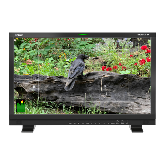
vMON-Series 12G/6G/3G/HD/SD-SDI, HDMI 4K/8K Video Monitors • vMON-170-4K vMON-170-8K • vMON-240-4K • vMON-270-4K vMON-270-8K • vMON-320-4K vMON-320-8K User Guide Part Number 821845, Revision A... - Page 2 In no event will Wohler Technologies, Inc. be liable for direct, indirect, special, incidental, or consequential damages resulting from any defect in the hardware, software, or its documentation, even if advised of the possibility of such damages.
-
Page 3: Table Of Contents
TABLE OF CONTENTS Table of Contents User Guide ..................1 TABLE OF CONTENTS ................3 Table of Contents ................... 3 CHAPTER 1: Installation ............... 5 Introduction ....................5 Overview .................... 5 Safety ......................5 Instructions ..................5 Screen Maintenance................6 Safety Symbols .................. - Page 4 Input Source Selection, Quad Split Mode ..........37 Input Source Selection, SDI SQD/2SI ............ 38 Configuration Settings................. 38 Function Key Settings ................. 39 CHAPTER 3: Technical Info ............... 40 Page 4 vMON-Series...
-
Page 5: Chapter 1: Installation
The vMON Series consists of 17”, 24” (4K only), 27”, or 32” 4K or 8K monitors which support a variety of 12G/6G/3G/HD/SD-SDI, HDMI, and SFP+ Cage source inputs. -
Page 6: Screen Maintenance
8. Use only the attachments/accessories specified by the manufacturer. 9. Unplug the equipment during lightning storms or when unused for long periods of time. 10. Refer all servicing to qualified service personnel. Servicing will be required under all of the following conditions: a. -
Page 7: Heat Dissipation
Table 1-1: Clearance Recommendations Clearance Surface 24” Front 3” Rear 2” Sides Heat Dissipation The ambient temperature inside the mounting enclosure should not exceed 40° Celsius (104° Fahrenheit). Important Heat generated by the power supplies and other components is vented by fans in the back of the unit. Therefore, as a safety precaution, you must allow proper ventilation on this surface. -
Page 8: Ices-003
radiate radio frequency energy and, if not installed and used in accordance with the instruction manual, may cause harmful interference to radio communications. Operation of this equipment in a residential area is likely to cause harmful interference, in which case users will be required to correct the interference at their own expense. -
Page 9: Chapter 2: Local Operation
CHAPTER 2: Local Operation Operation The vMON Series monitors can be operated easily and simply from controls on its front panel, as described in this chapter. Front Panel The front panel is shown in Figure 2-1. This panel image is representative of each of the monitors in the vMON series. - Page 10 use of two (left/right) speakers. The speaker response may be adjusted with tone controls in the Speaker Options menu. Refer to the Menu / Option Touchscreen section of Chapter 2. 4. Front Panel Controls: These controls are described in Figure 2-5 and the following text.
-
Page 11: Rear Panel
A typical vMON Rear Panels are shown in Figure 2-2. The number and type of connections on each Rear Panel may vary according to the features of each model. Figure 2-2: Typical vMON Series Rear Panels SDI SFP + 12G SDI In/Out... - Page 12 Important: By design, the supplied AC mains power cord will only plug into a three-prong grounded outlet for your safety. If the plug does not fit into the outlet, contact an electrician to replace the obsolete outlet. 2. DC Power: This is a 4-pin XLR-M jack. A 12V battery (not supplied) or a 12VDC power supply (not supplied) can be connected to this connector for operation when not connected to the AC mains.
- Page 13 GPI Ground return 9. LAN: This Ethernet port can be used for color correction, upgrading, or remote network control UMD via TSL5.0. Please contact Wohler Technical Service for further information. 10.SDI SFP+: This SFP+ cage accepts an optional 12G/6G/3G/HD/SD-SDI optical input module.
-
Page 14: Front Panel Control Operations
Front Panel Control Operations The location of the front panel knobs and buttons is shown in Figure 2-5. Figure 2-5: Front Panel Controls 1. Power: The Power button is used to turn the monitor on or off. When the monitor is connected to power, but the monitor is off, the indicator will light red. - Page 15 4. Menu/Exit: This button allows you to enter or exit the monitor set up menus or return to a previous menu. All of the functions and features of the monitor can be adjusted within the menu structure. Refer to the Menu and Options section of this chapter.
-
Page 16: Menus And Options
Menus and Options You may set most options or view a variety of system information using the self- contained menus. Figure 2-7 is a diagram of the menu arrangement, a tree showing how to reach any menu from the Main Menu. Hold the Source knob pressed for two seconds to access the Main Menu. -
Page 17: Menu Navigation
Menu Navigation Press the Menu/Exit button to access the Main Menu. Press it again to exit the menu system when you are finished. Rotate or press the U+D Image and the L+R Volume knobs to make your way through the submenus and make the changes you need to make. -
Page 18: Status Menu
Status Menu The first sub menu, Status is initially shown. It shows the status of various items. This menu is view-only and is not meant to be changed. The Status is shown in Figure 2-8. The items it contains are as follows: 1. -
Page 19: Video Payload Id/Hdmi Status Menu
Video Payload ID/HDMI Status Menu Rotate the U+D Image knob to highlight the VPID/HDMI Status selection and press the U+D Image knob to enter the submenu. This menu will either display the Video Payload ID/HDMI status for the selected HDMI or SDI source. This menu is shown in Figure 2-9. -
Page 20: Configuration Menu
4. SMPTE Standard: Display of the SMPTE protocol. (SDI only) 5. Color Depth: Display of the Color Depth of the signal. 6. Color Format: Display of the Color Format of the signal. 7. Data Level: Display of the Data Level of the signal. (HDMI only) 8. -
Page 21: Function Menu
monitor is power up. Either the Configuration will be unchanged from when power was turned off or a Configuration from 1 to 5 may be used. 6. Config1 Name: Use this selection to rename Config 1 with a name that perhaps relates to the input source selected in this Configuration. - Page 22 key is pressed. 2. S2: Use this to select which Configuration (1 - 5) will load when the S2 panel key is pressed. 3. S3: Use this to select which Configuration (1 - 5) will load when the S3 panel key is pressed.
-
Page 23: Source Menu
Source Menu Rotate the U+D Image knob to highlight the Source selection and press the U+D Image knob to enter the submenu. This menu will let you set up details about the input Sources. This menu is shown in Figure 2-12. Use the L+R Volume and U+D Image knobs to travel through the menu and make changes, as explained in the Menu Navigation section of this chapter. - Page 24 4. Win2 Source: This selects which input will display on Window 2, if it is enabled. The choices are SDI1, SDI2, SDI3, SDI4, SFP, and HDMI. 5. Win3 Source: This selects which input will display on Window 3, if it is enabled.
-
Page 25: Color Menu
Color Menu Rotate the U+D Image knob to highlight the Color selection and press the U+D Image knob to enter the submenu. This menu will let you set up details about the color display characteristics. This menu is shown in Figure 2-13. Use the L+R Volume and U+D Image knobs to travel through the menu and make changes, as explained in the Menu Navigation section of this chapter. - Page 26 a. Auto: The Data Level of the input signal is set automatically. b. Limited: 64-940 c. Extended: 64-1023 d. Full: 0-1023 e. SMPTE Full: 4-1019 5. Color Space: A choice of Color Space is offered: a. Auto: The Color Space of the input signal is matched automatically. b.
-
Page 27: Image Menu
5500K, or User 1 to User 6. You may customize the Color Temperature, save it to a corresponding User Mode (User1 through User6) in a configuration, assign that configuration to a S1 to S4 Select key, and then use that S1 to S4 key to load it. -
Page 28: Scope Menu
1:1. 3. Freeze: The ON or OFF setting will control whether to freeze the screen. 4. Over Scan: The ON or OFF setting will control whether Over Scan is enabled or not. 5. Mirror/Rotation: The settings are as follows: a. OFF: The orientation of the image on the screen is normal. b. - Page 29 a. OFF: The Waveform measurement is off and will not display. b. LUMA: The LUMA waveform will display. c. YCbCr: The YcbCr waveform will display. d. RGB: The RGB waveform will display. e. Quad Luma: This will display Quad Luma. This function is only available in Quad Mode.
-
Page 30: Assist Menu
Assist Menu Rotate the U+D Image knob to highlight the Assist selection and press the U+D Image knob to enter the submenu. This menu allows you to enable or disable the various Assist functions of the monitor. This menu is shown in Figure 2-16. Use the L+R Volume and U+D Image knobs to travel through the menu and make changes, as explained in the Menu Navigation section of this chapter. -
Page 31: Marker Menu
c. VITC2: The Time Code will be displayed as VITC2. d. LTC: The Time Code will be displayed as LTC. Note: Time Code cannot be displayed on HDMI signals. 8. Time Code Position: The Time Code display may be set to the Top of the screen or the Bottom of the screen. -
Page 32: Audio Menu
8. Box Display: The Box Display may be turned OFF or ON. 9. Box Center: The Box Center may be turned OFF or ON. 10. Box Mat: This is the color of the filling outside of the Box wire frame. It may be set to OFF, White, Black, Translucent, Red, Green, or Blue. -
Page 33: Cc Menu
input channel 1 through 16. 3. Right Audio Channel: The audio source of the right channel can be set to any input channel 1 through 16. 4. Audio Mode: The Audio Mode can be set to: a. Normal: Both left and right channels are output. b. -
Page 34: Umd Menu
1. Channel Source: The Source of the Closed Captions can be set to SDI1, SDI2, SDI3, or SDI4. 2. CC Mode: The three CC Mode settings are: a. OFF: Closed Captions will not be displayed. b. 708: 708 Closed Captions will be displayed. c. - Page 35 c. TSL4.0: The UMD characters can be set remotely using TSL4.0 protocol using an RS422 interface, 8-bits, 1 stop bit, even parity, 38400 baud. d. TSL5.0: The UMD characters can be set remotely using TSL5.0 protocol using the LAN interface, with the default IP address of the monitor: 192.168.1.155.
-
Page 36: System Menu
System Menu Rotate the U+D Image knob to highlight the System selection and press the U+D Image knob to enter the submenu. This menu allows you to set the various parameters that apply to the monitor as a system. This menu is shown in Figure 2- Use the L+R Volume and U+D Image knobs to travel through the menu and make changes, as explained in the Menu Navigation section of this chapter. -
Page 37: Commonly Used Setups
Disk or to via a USB connection to a PC. 9. USB Upgrade: You may upgrade the various firmware parts of the monitor via USB. The firmware to be upgraded includes FPGA, LUTs, OSD, EDP, APP, or all of the firmware. 10. -
Page 38: Input Source Selection, Sdi Sqd/2Si
3. Set the Display Mode to Quad, set Input Mode to Quad Input, set the Win1 Source to SDI 1, set the Win2 Source to SDI 2, set the Win3 Source to SDI 3, and set the Win4 source to HDMI. 4. -
Page 39: Function Key Settings
6. Go back to the Function submenu and set S2 to Config5. 7. Go to the Config submenu, set Save to Config5 and press the Volume Knob to save. 8. After saving, from now on pressing the S2 button will display the HDMI signal in Single Picture Mode, with the Color Space as U1_User1 and the Brightness set to 80. -
Page 40: Chapter 3: Technical Info
CHAPTER 3: Technical Info Table 3–1: vMON-170-4K, vMON-170-8K Specifications Specification Values/Domains 100 VAC to 240 VAC ± 10%, 50/60Hz or Power Requirements 12 VDC Power Consumption 50 Watts 17.1” x 12.6” x 5.9” (433mm x 321mm x Dimensions (H x W x D) 150mm) Shipping/Net Weight 17.2 lbs (7.8 kg) / 11.7 lbs (5.3 kg) - Page 41 Table 3–2: vMON-240-4K Specifications Specification Values/Domains 100 VAC to 240 VAC ± 10%, 50/60Hz or Power Requirements 12 VDC Power Consumption 70 Watts 22.7” x 15.8” x 5.9” (578mm x 401mm x Dimensions (H x W x D) 150mm) Shipping/Net Weight 25.2 lbs (11.4 kg) / 20 lbs (9.1 kg) Supplied Accessories AC Power Cord...
- Page 42 Table 3–3: vMON-270-4K, vMON-270-8K Specifications Specification Values/Domains 100 VAC to 240 VAC ± 10%, 50/60Hz or Power Requirements 12 VDC Power Consumption 63 Watts 26.3” x 17.4” x 6.3” (649mm x 441mm x Dimensions (H x W x D) 160mm) Shipping/Net Weight 30.9 lbs (14 kg) / 25.8 lbs (11.7 kg) Supplied Accessories...
- Page 43 Table 3–4: vMON-320-4K, vMON-320-8K Specifications Specification Values/Domains 100 VAC to 240 VAC ± 10%, 50/60Hz or Power Requirements 12 VDC Power Consumption 50 Watts 29.5” x 19.6” x 6.3” (750mm x 498mm x Dimensions (H x W x D) 160mm) Shipping/Net Weight 58.0 lbs (26.3 kg) / 27.7 lbs (12.5 kg) Supplied Accessories...
- Page 44 Figure 3–1: vMON-170-4K, vMON-170-8K Block Diagram Tally Light Inputs / Outputs Video Decoding 12G/6G/3G/HD/SD-SDI 1 In 12G/6G/3G/HD/SD-SDI 1 Out Digital Processing 12G/6G/3G/HD/SD-SDI 2 In LCD 17.1" Input 16:9 12G/6G/3G/HD/SD-SDI 2 Out Select With 16-Channel Panel Controls 3G/HD/SD-SDI 1 In Audio Meters 3G/HD/SD-SDI 1 Out 3G/HD/SD-SDI 2 In 3G/HD/SD-SDI 2 Out...
- Page 45 Figure 3–4: vMON-320-4K, vMON-320-8K Block Diagram Page 45 vMON-Series...
Need help?
Do you have a question about the vMON Series and is the answer not in the manual?
Questions and answers