
Related Manuals for peerless-AV DS-S555-4X3


Summary of Contents for peerless-AV DS-S555-4X3
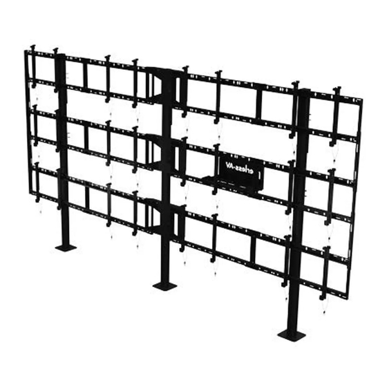
- Page 1 DS-S555-4X3 46" - 55" 1200 lb (117 - 140 cm) (544 kg) 2015-06-24 #:009-9117-6 (2020-01-14)
- Page 2 WARNING ENG - This product is designed to be installed on solid concrete. Hardware is included for solid concrete installation. Before installing make sure the supporting surface will support the combined load of the equipment and hardware. Screws must be tightly secured. Do not overtighten screws or damage can occur and product may fail.
- Page 3 Parts (Before beginning, make sure you have all parts shown below). Parts List Description Part # pedestal 147-T1426 column 146-T1131 extension 145-T1778 cover 145-T1809 side support bracket 145-T1807 vertical support bracket 145-T1806 left adaptor bracket 146-1609 right adaptor bracket 146-1608 computer cover 145-T1930 computer shelf...
- Page 4 K ( 6 ) I ( 1 ) J ( 1 ) dual cross computer cover computer shelf support L ( 3 ) M ( 6 ) cord extension N ( 3 ) bracket adaptor bracket, 4x2 configuration O ( 6 ) P ( 140 ) Q ( 56 ) R ( 12 )
- Page 5 Z (4) Do not fully tighten hardware P (4) U (2) TOP VIEW 2015-06-24 #:009-9117-6 (2020-01-14)
- Page 6 TIGHTEN CONNECTING HARDWARE 2015-06-24 #:009-9117-6 (2020-01-14)
- Page 7 1/8" 1/8" (3mm) (3mm) Q (4) P (6) F (3) TIGHTEN CONNECTING HARDWARE 2015-06-24 #:009-9117-6 (2020-01-14)
- Page 8 R (4) M (2) O (2) TIGHTEN CONNECTING HARDWARE TOP VIEW 2015-06-24 #:009-9117-6 (2020-01-14)
- Page 9 Use metric formula below and diagram to right to determine hole pattern required for center vertical support bracket. All dimensions are metric. BACK OF DISPLAY Use the outside mounting holes when… Use the inside mounting holes when… a x 4 > 4368mm and a x 3 + b < 4318mm a x 4 >...
- Page 10 TIGHTEN CONNECTING HARDWARE TOP VIEW 2015-06-24 #:009-9117-6 (2020-01-14)
- Page 11 WARNING ENG - When installing Peerless mounts on a concrete floor, the floor must be at least 8" thick with a minimum compressive strength of 2000 psi. Never attach concrete expansion anchors to concrete covered with plaster, drywall, or other finishing material. 2015-06-24 #:009-9117-6 (2020-01-14)
- Page 12 Drill mounting holes into supporting surface (3" (76mm) minimum depth required). Align base. Mark mounting holes. 3/8" (10mm) 3" 3/8" (76mm) (10mm) 55.00" 55.00" (1397mm) (1397mm) 3/8" (10mm) AA (12) Align base. Install using concrete anchors provided. 55.00" (1397mm) 55.00" (1397mm) ENG Maximum 35 ft •...
- Page 13 TIGHTEN CONNECTING HARDWARE K (2) 2015-06-24 #:009-9117-6 (2020-01-14)
- Page 14 TIGHTEN CONNECTING HARDWARE K (2) 2015-06-24 #:009-9117-6 (2020-01-14)
- Page 15 TIGHTEN CONNECTING HARDWARE K (2) 2015-06-24 #:009-9117-6 (2020-01-14)
- Page 16 Q (8) E (4) P (2) TIGHTEN CONNECTING HARDWARE Q (2) P (8) 2015-06-24 #:009-9117-6 (2020-01-14)
- Page 17 11-1 Center adaptor brackets vertically on back of screen. 11-2 2015-06-24 #:009-9117-6 (2020-01-14)
- Page 18 12-1 "LOCKED" POSITION Must hang displays on bottom row first; Secure pin in "locked" position. 12-2 "LOCKED" POSITION Must hang displays on middle row second; Secure pin in "locked" position. 2015-06-24 #:009-9117-6 (2020-01-14)
- Page 19 12-3 "LOCKED" POSITION Must hang displays on top row last; Secure pin in "locked" position. 12-4 OPTIONAL: Insert M5 x 10mm type-F socket pin screws (S) to lock latches. "LOCKED" POSITION 2015-06-24 #:009-9117-6 (2020-01-14)
- Page 20 Display adjustment TILT FORWARD SIDE SIDE SIDE TILT BACKWARD TILT RIGHT TILT LEFT SIDE DOWN ROTATE LEFT ROTATE RIGHT 2015-06-24 #:009-9117-6 (2020-01-14)
- Page 21 2015-06-24 #:009-9117-6 (2020-01-14)
- Page 22 15-1 1/8" (3mm) S (2) 15-2 TIGHTEN CONNECTING HARDWARE 2015-06-24 #:009-9117-6 (2020-01-14)
- Page 23 Route cables through cord brackets. 2015-06-24 #:009-9117-6 (2020-01-14)
- Page 24 (from date of the original installation of the product). At its option, Peerless-AV will repair or replace, or refund the purchase price of, any product which fails to conform with this warranty.
Need help?
Do you have a question about the DS-S555-4X3 and is the answer not in the manual?
Questions and answers