
Related Manuals for peerless-AV DS-S555-4X2


Summary of Contents for peerless-AV DS-S555-4X2
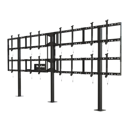
- Page 1 DS-S555-4X2 46" - 55" 800 lb (117 - 140 cm) (363 kg) 2014-07-29 #:009-9090-4 (2018-03-08)
- Page 2 WARNING ENG - Do not begin to install product until you have read and understood the instructions and warnings contained in this user guide. Always use an assistant or mechanical lifting equipment to safely lift and position equipment. This product must be installed onto flat, hard, level surface to prevent tipping. Use with heavier displays may result in instability causing tip over resulting in death or serious injury.
- Page 3 Tools Needed for Assembly. To properly tighten screws: Tighten until screw head makes contact, then tighten another 1/2 turn. Do not overtighten screws. 3/8" (10mm) +1/2 3/8" (10mm) 2014-07-29 #:009-9090-4 (2018-03-08)
-
Page 4: Parts List
Parts (Before beginning, make sure you have all parts shown below). Parts List Description Part # pedestal 146-T1132 column 146-T1131 cover 145-T1809 side support bracket 145-T1807 vertical support bracket 145-T1806 left adaptor bracket 146-1609 right adaptor bracket 146-1608 computer cover 145-T1930 computer shelf 145-T1931... - Page 5 H ( 1 ) I ( 1 ) J ( 4 ) computer cover computer shelf dual cross support K ( 6 ) L ( 6 ) M ( 2 ) cord knob bracket, 4x2 bracket configuration N ( 84 ) O ( 36 ) P ( 12 ) Q ( 18 )
- Page 6 W (4) 2014-07-29 #:009-9090-4 (2018-03-08)
- Page 7 1/8" 1/8" (3mm) (3mm) O (4) N (6) TIGHTEN CONNECTING HARDWARE 2014-07-29 #:009-9090-4 (2018-03-08)
-
Page 8: Top View
P (4) K (2) L (2) TIGHTEN CONNECTING HARDWARE TOP VIEW 2014-07-29 #:009-9090-4 (2018-03-08) - Page 9 Use metric formula below and diagram to right to determine hole pattern required for center vertical support bracket. Repeat (x2). All dimensions are metric. BACK OF DISPLAY Use the outside mounting holes when… Use the inside mounting holes when… a x 4 > 4368mm and a x 3 + b < 4318mm a x 4 >...
- Page 10 WARNING ENG - When installing Peerless mounts on a concrete floor, the floor must be at least 8" thick with a minimum compressive strength of 2000 psi. Never attach concrete expansion anchors to concrete covered with plaster, drywall, or other finishing material. ADVERTENCIA ESP - Cuando vaya a instalar soportes de techo de Peerless en techos de concreto, los techos tienen que tener, por lo menos, 8"...
- Page 11 Drill mounting holes into supporting surface (3" (76mm) minimum depth required). Align base. Mark mounting holes. 3/8" (10mm) 3/8" 3" (10mm) (76mm) 55.00" 55.00" (1397mm) (1397mm) 3/8" (10mm) Tighten. X (12) Align base. Install using concrete anchors provided. 55.00" (1397mm) 55.00"...
- Page 12 TIGHTEN CONNECTING HARDWARE J (2) TIGHTEN CONNECTING HARDWARE J (2) 2014-07-29 #:009-9090-4 (2018-03-08)
- Page 13 O (4) D (2) N (2) N (4) O (2) 2014-07-29 #:009-9090-4 (2018-03-08)
- Page 14 Center adapter brackets vertically on back of screen. 2014-07-29 #:009-9090-4 (2018-03-08)
- Page 15 "LOCKED" POSITION Must hang displays to bottom row first; Secure pin in "locked" position. "LOCKED" POSITION Must hang displays on top row last; Secure pin in "locked" position. 2014-07-29 #:009-9090-4 (2018-03-08)
- Page 16 Must hang displays on top row second; Secure pin in "locked" position. OPTIONAL: Insert M5 x 10mm type-F socket pin screws (Q) to lock latches. "LOCKED" POSITION 2014-07-29 #:009-9090-4 (2018-03-08)
-
Page 17: Display Adjustment
Display Adjustment TILT FORWARD SIDE SIDE SIDE TILT BACKWARD TILT RIGHT TILT LEFT SIDE DOWN ROTATE LEFT ROTATE RIGHT 2014-07-29 #:009-9090-4 (2018-03-08) - Page 18 2014-07-29 #:009-9090-4 (2018-03-08)
- Page 19 11-1 1/8" (3mm) Q (2) 11-2 TIGHTEN CONNECTING HARDWARE 2014-07-29 #:009-9090-4 (2018-03-08)
- Page 20 Route cables through cord brackets. 2014-07-29 #:009-9090-4 (2018-03-08)
- Page 21 This page intentionally left blank. 2014-07-29 #:009-9090-4 (2018-03-08)
- Page 22 This page intentionally left blank. 2014-07-29 #:009-9090-4 (2018-03-08)
-
Page 23: Limited Five-Year Warranty
LIMITED FIVE-YEAR WARRANTY Peerless Industries, Inc. (“Peerless”) warrants to original end-users of Peerless products will be free from defects in material and ® workmanship, under normal use, for a period of five years from the date of purchase by the original end-user (but in no case longer than six years after the date of the product's manufacture). - Page 24 Peerless-AV Peerless-AV Europe Peerless-AV de Mexico 2300 White Oak Circle Unit 3 Watford Interchange, Ave de las Industrias 413 Aurora, IL 60502 Colonial Way, Watford, Herts, Parque Industrial Escobedo Email: tech@peerlessmounts.com WD24 4WP, United Kingdom Escobedo N.L Mexico 66062 Ph: (800) 865-2112...
Need help?
Do you have a question about the DS-S555-4X2 and is the answer not in the manual?
Questions and answers