Table of Contents
Advertisement
Quick Links
One Technology Way • P.O. Box 9106 • Norwood, MA 02062-9106, U.S.A. • Tel: 781.329.4700 • Fax: 781.461.3113 • www.analog.com
FEATURES
Simple power connection using 6 V wall adapter and
on-board LDO voltage regulators
LDOs are easily bypassed for power measurements
5 ac-coupled differential LVDS SMA connectors
7 LVDS differential headers for additional outputs
SMA connectors for
2 reference inputs
Charge pump output
Clock distribution input
USB connection to PC
Microsoft Windows-based evaluation software
with simple graphical user interface
On-board PLL loop filter
Easy access to digital I/O and diagnostic signals via I/O
header
Status LEDs for diagnostic signals
APPLICATIONS
Clocking of analog-to-digital and digital-to-analog
converters up to 2.9 GHz
Networking and communications line cards
Test and measurement equipment
Wireless base stations, controllers
Clock cleanup/jitter attenuation
Clock distribution
Please see the last page for an important warning and disclaimers.
AD9522-x Evaluation Board
GENERAL DESCRIPTION
The AD9522-x (hereafter referred to as AD9522) is a very low
noise PLL clock synthesizer featuring an integrated VCO, clock
dividers, and up to 24 outputs. The AD9522 features automatic
holdover and a flexible reference input circuit allowing for very
smooth reference clock switching. The AD9522 family also
features the necessary provisions for an external VCXO.
The AD9522 evaluation board is a compact, easy to use plat-
form for evaluating all features of the AD9522. This user guide
covers all six versions of the AD9522 family.
Although the Quick Start Guide to the AD9522 PLL section
applies specifically to the AD9522-4, increasing the N (feedback)
divider and channel divider increases the VCO frequency to the
allowable frequency range of other AD9522 versions.
For the AD9522-5, which lacks the internal VCO, certain portions
of this user guide that apply to the internal VCO (such as VCO
calibration) can be ignored.
For convenience, detailed information from the AD9522 data sheet
has been included here. Use this user guide in conjunction with
the AD9520 and AD9522 data sheets and software documenta-
tion available at www.analog.com.
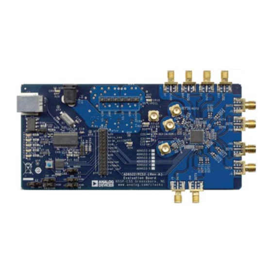
AD9522 EVALUATION BOARD
Figure 1.
Rev. 0 | Page 1 of 16
Evaluation Board User Guide
UG-077
Advertisement
Table of Contents

Related Manuals for Analog Devices AD9522 Series


Summary of Contents for Analog Devices AD9522 Series
-
Page 1: Features
Evaluation Board User Guide UG-077 One Technology Way • P.O. Box 9106 • Norwood, MA 02062-9106, U.S.A. • Tel: 781.329.4700 • Fax: 781.461.3113 • www.analog.com AD9522-x Evaluation Board FEATURES GENERAL DESCRIPTION The AD9522-x (hereafter referred to as AD9522) is a very low Simple power connection using 6 V wall adapter and on-board LDO voltage regulators noise PLL clock synthesizer featuring an integrated VCO, clock... -
Page 2: Table Of Contents
UG-077 Evaluation Board User Guide TABLE OF CONTENTS Features ....................1 Reference (R) Divider Window ...........9 Applications ..................1 Feedback (N) Divider Window ..........10 General Description ................. 1 R and N Delay Window ............. 10 AD9522 Evaluation Board ............... 1 Phase Frequency Detector (PFD) Window ...... -
Page 3: Evaluation Board Hardware
Evaluation Board User Guide UG-077 EVALUATION BOARD HARDWARE The following instructions are for setting up the physical Connect an oscilloscope, spectrum analyzer, or other lab connections to the AD9522 evaluation board. equipment to any of the J0 to J9 SMA connectors on the right side of the board. -
Page 4: Evaluation Board Software
Double-click AD9522Eval_Setup1.1.0.exe. Follow the installation instructions. The default location for the evaluation software is C:\Program Files\Analog Devices\ AD9522 Eval Software\. RUNNING THE SOFTWARE Power up and connect the evaluation board to the PC. See the Evaluation Board Hardware section for details on the various connectors on the evaluation board. -
Page 5: Quick Start Guide To The Ad9522 Pll
Evaluation Board User Guide UG-077 QUICK START GUIDE TO THE AD9522 PLL When the evaluation software is installed, the evaluation board is connected, and the software is loaded, use the following steps to configure and lock the PLL. These steps assume that the input signal is present, the evaluation board has not been modified, and that the PLL loop filter is suitable for the user’s application. - Page 6 UG-077 Evaluation Board User Guide Program the R (reference) divider by clicking the R DIVIDER are not powered down can be a source of unwanted noise box at the top of the main window. Set the desired value in the output signals. (72, in this case) and click OK (see Figure 13).
-
Page 7: Evaluation Software Components
Evaluation Board User Guide UG-077 EVALUATION SOFTWARE COMPONENTS MAIN WINDOW Figure 8. AD9522 Evaluation Software Main Window Rev. 0 | Page 7 of 16... -
Page 8: Pll Reference Input Window
UG-077 Evaluation Board User Guide The AD9522 evaluation software is composed of subsections Select Enable REF 1, or Enable REF 2, or both to enable the that correspond to the AD9522’s major functional blocks. These appropriate reference input, and click OK when finished. If a subsections are listed in the following sections, and each of differential input is used, select the Use Differential Ref Mode these has its own window. -
Page 9: Refmon, Status, And Ld Buttons
Evaluation Board User Guide UG-077 REFMON, STATUS, AND LD BUTTONS EEPROM CONTROL WINDOW These three blue buttons allow you to select which signals appear at the REFMON, STATUS, and LD pins at Connector P1. Connector P1 is located in the center of the evaluation board. The pins in the left column of Connector P1 are ground pins, and the ones in the right column are signal pins. -
Page 10: Feedback (N) Divider Window
UG-077 Evaluation Board User Guide FEEDBACK (N) DIVIDER WINDOW R AND N DELAY WINDOW Figure 14. AD9522 Reference Divider Window Figure 15. AD9522 N Delay Window The reference divider window shown in Figure 14 is accessed by clicking the N DIVIDER box. It allows you to set the feedback The N delay window shown in Figure 15 is accessed by clicking divider. -
Page 11: Charge Pump Window
Evaluation Board User Guide UG-077 CHARGE PUMP WINDOW VCO CALIBRATION WINDOW Figure 19. AD9522 VCO Calibration Window Figure 17. AD9522 Charge Pump Window The VCO calibration window shown in Figure 19 is accessed by The Charge Pump Setup window shown in Figure 17 is clicking the Cal VCO button on the main window. -
Page 12: Output Driver Window
UG-077 Evaluation Board User Guide OUTPUT DRIVER WINDOW LVDS and CMOS outputs have different termination require- ments, and OUT9 through OUT11 have been terminated differently from OUT0 through OUT8. OUT0 through OUT8 are ac-coupled, and this termination scheme is ideal for LVDS drivers. However, this scheme may degrade CMOS driver performance. -
Page 13: Evaluation Software Menu Items
Evaluation Board User Guide UG-077 EVALUATION SOFTWARE MENU ITEMS Figure 24. Menu Bar MENU BAR Configure Serial Port File Menu The I/O Interface window allows you to control how the USB controller interacts with the AD9522 serial port. The file menu has the following options: Load Setup Selecting Load Setup loads a previously saved AD9522 setup file (.stp). -
Page 14: Ad9522 Pll Loop Filter
UG-077 Evaluation Board User Guide AD9522 PLL LOOP FILTER The AD9522 PLL requires an external loop filter whose compo- The user should not consider these recommendations as a nents are tailored for different applications. The third-order substitute for using ADIsimCLK™ to determine the best loop passive configuration shown in Figure 27 usually offers the best filter for a given application. -
Page 15: Using The Evaluation Board To Program An Ad9522 On A User Board
Evaluation Board User Guide UG-077 USING THE EVALUATION BOARD TO PROGRAM AN AD9522 ON A USER BOARD This guide shows how to use an AD9522 evaluation board to Click Reset Serial Port, and then click Detect Current program an AD9522 on a customer board via the I C interface. -
Page 16: Ad9522 Binary File Generation
Information furnished by Analog Devices is believed to be accurate and reliable. However, no responsibility is assumed by Analog Devices for its use, nor for any infringements of patents or other rights of third parties that may result from its use. Analog Devices reserves the right to change devices or specifications at any time without notice.
Need help?
Do you have a question about the AD9522 Series and is the answer not in the manual?
Questions and answers