
Related Manuals for EXFO OmniCure R2000


Summary of Contents for EXFO OmniCure R2000
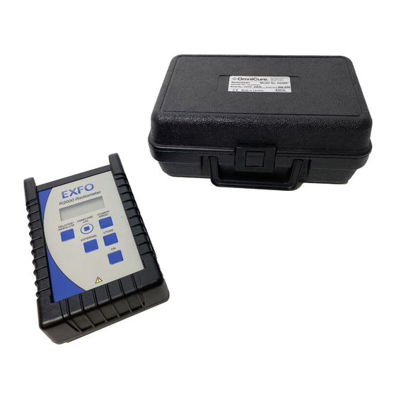
- Page 1 R2000 Radiometer UV/VISIBLE RADIOMETER 250 – 1000 nm USER’S GUIDE Printed in Canada 035-00243 Rev. 4...
- Page 2 10 Mb for Software Installation 20 Mb for Data Storage SVGA video 800x600 resolution One available RS-232 Port Place CD Here Trademarks ® OmniCure is a trademark of EXFO Photonic Solutions Inc. All other product names are trademarks of their respective owners...
-
Page 3: Table Of Contents
Table of Contents INTRODUCTION ..............3 CONTROL FUNCTIONS & FEATURES ......4 FAMILIARIZING YOURSELF WITH THE R2000 RADIOMETER ................. 6 USING THE R2000 RADIOMETER ......10 R2000 R ON ....10 URNING THE ADIOMETER ..........10 ALIBRATION ......11 SING IGHT UIDE DAPTERS... - Page 4 7 TECHNICAL SPECIFICATIONS*........39 ............ 39 PTICAL ..........40 LECTRICAL ..........40 ECHANICAL RS-232 C : ....40 ONFIGURATION ......41 NVIRONMENTAL ONDITIONS : ....41 EGULATORY OMPLIANCE AFETY WEEE D (2002/96/EU) ..... 44 IRECTIVE ACCESSORIES..............46 WARRANTY ................48 Page 2 of 50...
-
Page 5: Introduction
It joins the EXFO Life Sciences & Industrial Division family of spot cure and illumination systems, offering the same high level of innovation, quality and reliability that customers have come to expect from EXFO Life Sciences &... -
Page 6: Control Functions & Features
Control Functions & Features Features Benefits Provides accurate Versatile measurement broadband capability suitable for many measurements different light between 250-1000nm Sources Measures power or Allows for industry specific irradiance measures Optical interface Eliminates beam intensity collects light over a and radiance dependence large area Auto-ranging Maintains precision over full... - Page 7 Features Benefits Designed to meet IEC, Ready for use worldwide Canadian and US Standards and CE marking requirements Calibration traceable to Quality assurance NIST Calibration period of 12 Lower cost of operation months Auto turn off Extends battery life and makes operation easier IR Link Provides wireless connection...
-
Page 8: Familiarizing Yourself With The R2000 Radiometer
Familiarizing yourself with the R2000 Radiometer Thumbscrew Light Guide Adapter IR Window Optical Input Port Remote Input Display Connector Note: For connection of optional cure site & Front cure ring Keypad radiometer only RS-232 Connector Rubber Boot Page 6 of 50... - Page 9 6’ 9-Pin style cable (RS-232) • CD with GUI software and programming notes • Carrying case • Light Guide Adapter Interfaces EXFO Life Sciences & Industrial Division standard size light guides to the optical input port to promote accurate light delivery into R2000 Radiometer.
- Page 10 Front Keypad The front keypad is comprised of 6 independent membrane-style switches, Pressing this button will turn the R2000 Radiometer on. RELATIVE / ABSOLUTE Each press of this button toggles between relative and absolute mode. The default setting is Absolute mode. Relative mode displays...
- Page 11 Rubber Boot A protective, flexible cover that allows the radiometer to stand upright on a flat surface. The rubber boot is optional and can be removed when not desired. When the boot is utilized, the RS-232 connector and Remote Input connector are accessible by lifting flap on the right side of the boot.
-
Page 12: Using The R2000 Radiometer
Using the R2000 Radiometer Turning the R2000 Radiometer ON The R2000 Radiometer is fitted with an ON switch located on the front keypad. Press and release the button. All segments on the display illuminate for 1 second. Note: If a light guide adapter is installed in the optical port, the display will flash the diameter of the light guide adapter for 3 sec. -
Page 13: Using Light Guide
The calibration is traceable to NIST and a calibration certificate is included at each calibration cycle. Calibration is authorized only by a certified EXFO service center. When calibration is due contact EXFO for a return authorization number. Refer to Section 9.0. -
Page 14: Using Non -Standard
In order to use non-standard size light guides with the R2000 Radiometer a custom light guide adapter is required. Contact EXFO Life Sciences & Industrial Division for further details. Refer to Section 9. Note: The diameter of the light guide must be entered in the PC software before the light guide is used with its custom adapter. -
Page 15: Measuring Irradiance
Measuring Irradiance When measuring irradiance, the display will show the measurement in either mW/cm or W/cm If the display is not showing the “ /cm ”, it indicates that the R2000 Radiometer is in Power mode. Simply press POWER/IRRAD keypad button toggle into... -
Page 16: Measuring Ina
Select either Power or Irradiance mode from the keypad. Adjust the optical source to the desired reference level, and then press the Relative/Absolute button. The R2000 Radiometer will toggle to Relative mode. All subsequent measurements will be displayed as a percentage of the reference. - Page 17 Radiometer. External radiometer devices are available from EXFO Life Sciences & Industrial Division as custom ordered items. Press the EXTERNAL keypad button. The display will show the EXT icon and a number (starting at 1), that corresponds to the external radiometer sensor being detected.
- Page 18 The following illustrates the use of the EXTERNAL feature with four external radiometer devices. Sensor Sensor Sensor Sensor Dongle R2000 Connection via Remote Input Jack Page 16 of 50...
-
Page 19: 4.11 Storing Data
With each press of the EXTERNAL keypad button, the display will show, Reading Reading Reading Reading Reading Internal Detector Storing Data 4.11 Storing Data The R2000 Radiometer is able to store measurements based on what is being detected at the time the STORE button is pressed. -
Page 20: Interfacing With
downloaded into a Data Log as seen on the R2000 Control Panel (via the GUI software provided). stored readings can only be viewed by downloading to a Once a reading has been stored, it can not be viewed on the R2000 Radiometer display. 4.12 Interfacing with Compatible OmniCure UV Curing Systems Refer to the OmniCure Curing System User Guide. - Page 21 To interface via the RS-232: Plug the phono-style cable into the RS-232 connector located on the side of the unit and to the Audio Jack connector located on the front panel side of the OmniCure UV Curing System. The cable supplied is six feet in length.
-
Page 22: Using The R2000 R
The SET icon will cease to flash, while remaining illuminated. The set point can be also be programmed by the PC. 4.14 Using the R2000 Radiometer with a PC The following are the minimum requirements for a PC to be used with the R2000 Control Panel software: •... - Page 23 8) To access the control panel software program, click on the Windows Start menu and select: programs/ EXFO ►/ R2000 Control Panel. A screen with a title bar displaying “R2000 Control Panel” will appear. Click on Connect at the top of the screen. The R2000 Control Panel will open when there is a successful connection.
- Page 24 If a problem connecting occurs, the PC may display a ‘Failed to open COM port’ message. Click ‘OK’. Select from the File pull down menu – COM Ports. Ensure that the applicable COM port is checked and cable connected corresponding plug.
- Page 25 The following illustrates the R2000 Control Panel: Based on the settings and data being read from the R2000 Radiometer, the information will display in the respective areas of the Control Panel. Some data is user-defined such as: • Set Point •...
- Page 26 If the transfer fails, the background colour reverts to the default colour but the foreground colour becomes red. A dialogue box will appear indicating that the request failed. Click OK to continue. The Optical Data frame displays a combination of real- time data as it pertains to readings being taken from the R2000 Radiometer as well as user-defined fields.
- Page 27 Relative Reference – User defined; enter the desired power reference to be used in Relative mode. Custom Adapter Diameter – User defined; when using a non-standard light guide with the R2000 Radiometer enter the applicable diameter of the customized light guide adapter.
- Page 28 If the RTC date/time stamp is not the same as the PC clock use the Set R2000 Radiometer Clock function under the File menu to synchronize. Status The Status frame indicates the applicable status modes of the R2000 Radiometer. Page 26 of 50...
- Page 29 Cal Required – When checked indicates that the R2000 Radiometer is past its recommended calibration date. This is equivalent to the ‘CAL’ message that appears on the R2000 Radiometer’s display. Low Battery – When checked indicates that the battery is low and should be replaced. This is equivalent to the ‘BAT’...
- Page 30 Menu Functions To operate and control the R2000 Radiometer from the PC, select desired menu functions located across the top of the R2000 Control Panel. Display Select the Display menu and then select the desired mode of Power, Irradiance, Absolute or Relative. Selected options are indicated as checked boxes in the Display frame.
- Page 31 Lockout Select Lockout menu option to disable certain features or functionality from the front keypad of the R2000 Radiometer. Select from the available list in the pull-down menu. The selections that are checked are indicated in the Lockout frame. If a box is checked, this means that this function will not operate from the front keypad of the R2000 Radiometer.
- Page 32 Get LGA In the event that the size of the light guide adapter must be re-detected remotely, it can be obtained from the Get LGA menu option at the top of the screen. Selecting this will re-detect the colour of the light guide adapter and hence the size of the light guide installed in the R2000 Radiometer.
- Page 33 Select Log Readings During OMNICURE CAL to log each calibration point into the Data Log during a calibration cycle with a compatible OmniCure UV Curing System. The following is a sample screen shot of the Data Log, Page 31 of 50...
- Page 34 Power Down Select this menu option to power down the R2000 Radiometer. Page 32 of 50...
-
Page 35: Glossary Of Symbols And Safety
Glossary of Symbols and Safety Precautions CAUTION – RISK OF DANGER Consult accompanying documents CAUTION! Never look into the light emitting end of a light guide. The light could severely damage the cornea and retina of the eye if the light is observed directly. - Page 36 SAFETY PRECAUTIONS: WARNING! Should the R2000 Radiometer be used in a manner not specified by EXFO Life Sciences & Industrial Division, the protection provided by the equipment may be impaired. WARNING! The R2000 Radiometer is supplied with a lithium battery. Lithium batteries present a potential fire, explosion or severe burn hazard.
-
Page 37: Troubleshooting
Troubleshooting Error Messages Display Indicates ‘Adc’ Message If an Adc message appear on the display it indicates that there is an internal problem with the unit during power up. If this occurs, it is recommended that the R2000 Radiometer be serviced. See Section 9. Display Indicates ‘BAT’... -
Page 38: Cal ' Message
Place the R2000 Radiometer back into the rubber boot if desired. Used batteries are not to be discarded. Return to the nearest authorized EXFO service center for disposal/ re- cycling. Use appropriate safety measures found in Section 5. Display Indicates ‘Cal’ Message... -
Page 39: Lg' Message
If the SET icon is displayed with the Err message it indicates that a SET function was not completed successfully. If the EXT icon is illuminated on the display with the Err message displayed indicates that R2000 Radiometer was unable to communicate with an external adapter. -
Page 40: Lga' Message
Display Indicates ‘LGA’ Message This message as illustrated below will appear when the R2000 Radiometer is unable to detect the colour of the light guide adapter. If this message appears it is recommended that the light guide adapter be cleaned or replaced. -
Page 41: Technical Specifications
7 Technical Specifications* Optical Wavelength Range: 250-1000 nm Maximum Range: Power: 1mW – 15W Irradiance: 2mW/cm – 475W/cm Resolution: Power Range: 0.007-1.999mW 0.01mW 2.00-19.99mW 0.01mW 20-199.9mW 0.1mW 200-1999mW 2.00-19.99W 10mW Accuracy: ± 5% typical, ± 10% maximum Auto-ranging: Power: 1 – 999 mW, 1 –... -
Page 42: Electrical
Electrical Battery Type: 3.6 volt Lithium, non-rechargeable 2.2 Ah I/O Ports: IrDA compliant transceiver Connect only to RS-232 Pin 1 (Shield) – GND equipment that Pin 2 (Ring) – Tx is IEC 950 Pin 3 (Tip ) – Rx compliant Remote Input Port: 6-Pin Mini-DIN connector (use only with... -
Page 43: Environmental Conditions
Environmental Conditions Operating Environment Conditions Installation Category II Pollution Degree 2 Ambient Temperature: 10 to 35 degrees Celsius Relative Humidity: 15% to 95% (non-condensing) Atmospheric Pressure: 700 to 1060 hPa Altitude: 2000 meters (maximum) Transport and Storage Conditions Temperature: -10 to 60 degrees Celsius Relative Humidity: 10% to 100% (non- condensing) - Page 44 The IrDA-Data SIR mode compliant transceiver that is used to form an IR link to an OmniCure Series 2000 is certified to meet the Class 1 eye safety specifications of IEC 825-1/ EN 60825-1. Electromagnetic Compatibility: EN 61326-1: 2001/ A1/ A2 Electromagnetic Compatibility Immunity Testing-Measurement, Control and Laboratory...
- Page 45 China RoHS The following table contains substance information for the Omnicure R2000 as required by China RoHS regulations. 有毒有害物质名称及含量的标识格式 有毒有害物质或元素 多溴二 六价 多溴 部件名称 铅 汞 镉 苯醚 铬 联苯 ) ) ) (PBDE (Cr6+) (PBB) ) 显示器印刷电 ○ ○...
-
Page 46: Weee Directive (2002/96/Eu)
7.7 WEEE Directive (2002/96/EU) The symbol above indicates that this product should not be disposed of along with municipal waste, that the product should be collected separately, and that a separate collection system exists for all products that contain this symbol within member states of the European Union. - Page 47 • Consult the dealer or an experienced radio/TV technician for help WARNING Changes or modifications not expressly approved by EXFO Life Sciences & Industrial Division could void the user’s authority to operate the equipment. Page 45 of 50...
-
Page 48: Accessories
Accessories EXFO Life Sciences and Industrial Division carries a full line of replacement parts, supplies and accessories for the R2000 Radiometer. team light-based technology experts recommend light delivery solutions for a range of manufacturing, illumination and biomedical applications. We also welcome custom requests for unique light delivery requirements. - Page 49 Optional Adapters Optical accessories provide solutions to a wide range of situations. Optical accessories include the Proximity Measurement Adapter and the optional Lamp Output Adapter. These adapters expand the range of measurement geometries that can be accommodated. 5mm Proximity Adapter Reorder No.
-
Page 50: Warranty
Warranty EXFO warrants, to the original purchaser for a period of one (1) full year, calculated from the date of purchase, that the equipment sold is free from defects in material and workmanship. In the event of a claim under this guarantee, the... - Page 51 There are no User serviceable parts within the R2000 Radiometer. Opening the main R2000 Radiometer enclosure will void the warranty. Contact Information EXFO LIFE SCIENCES & INDUSTRIAL DIVISION 2260 Argentia Road Mississauga, Ontario L5N 6H7 CANADA Tel.:+1 905 821-2600 Toll.:+1 800 668-8752 (USA and Canada) Fax:+1 905 821-2055 www.exfo-uv.com...
- Page 52 EXFO Asia Pacific Tel.: +86 (10) 6849 2738 PTE. Ltd. Beijing Fax: +86 (10) 6849 2662 Representative Office Beijing New Century Hotel Office Tower, Room 1754-1755 No 6. Southern Capital Gym Road Beijing 100044 P.R. CHINA Cadence P - 65 6779 0900...
Need help?
Do you have a question about the OmniCure R2000 and is the answer not in the manual?
Questions and answers