Table of Contents
Advertisement
Quick Links
Advertisement
Table of Contents

Related Manuals for EXFO PPM1


Summary of Contents for EXFO PPM1
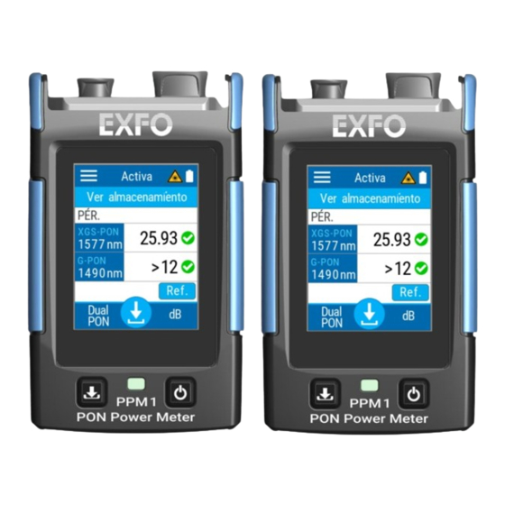
- Page 1 User Guide PPM1 PON Power Meter www.EXFO.com...
- Page 2 EXFO Inc. (EXFO). Information provided by EXFO is believed to be accurate and reliable. However, no responsibility is assumed by EXFO for its use nor for any infringements of patents or other rights of third parties that may result from its use.
-
Page 3: Table Of Contents
Contents Contents Regulatory Information ......................vi 1 Introducing the PPM1 PON Power Meter ............1 Main Features .........................2 Available Options ........................4 LED Indicator Description .......................5 Battery Status Icon Description ....................6 Power Sources ........................7 Temperature Management .....................8 Technical Specifications ......................8 Conventions ..........................9 2 Safety Information ..................11... - Page 4 Contents 3 Setting up and Using Your PPM1 ...............19 Turning on Your Unit ......................19 Cleaning and Connecting Optical Fibers ................20 Turning off Your Unit ......................22 Understanding the Main Window ..................23 Selecting the Power Meter Mode ..................24 Configuring the Auto-Off Value ....................26 Adjusting Brightness ......................28...
- Page 5 Viewing System Information ....................102 Transportation ........................103 7 Warranty ....................105 General Information ......................105 Gray Market and Gray Market Products ................106 Liability ..........................107 Exclusions ...........................107 Certification ........................107 Service and Repairs ......................108 EXFO Service Centers Worldwide ..................109 Index .......................111 PON Power Meter Page v...
-
Page 6: Regulatory Information
USA Electromagnetic Interference Regulatory Statement Electronic test and measurement equipment is exempt from FCC part 15, subpart B compliance in the United States of America. However, EXFO Inc. makes reasonable efforts to ensure compliance to the applicable standards. The limits set by these standards are designed to provide reasonable protection against harmful interference when the equipment is operated in a commercial environment. - Page 7 Regulatory Information Canada Electromagnetic Interference Regulatory Statement This equipment generates, uses, and can radiate radio frequency energy and, if not installed and used in accordance with the instruction manual, may cause harmful interference to radio communications. Operation of this equipment in a residential area is likely to cause harmful interference. Cet équipement génère, utilise et peut émettre de l'énergie radio-fréquence et, s'il n'est pas installé...
- Page 8 Regulatory Information This is a class A, group 1 product. Ceci est un produit de classe A, groupe 1. Class A equipment: Equipment that is, by virtue of its characteristics, highly unlikely to be used in a residential environment, including a home business shall be classified as class A and shall comply with the class A limits specified in the applicable ICES standard.
- Page 9 Regulatory Information Group 1 equipment: group 1 contains all equipment which is not classified as group 2 equipment, and includes equipment such as laboratory and scientific equipment, industrial process, measurement and control equipment. Group 2 equipment: group 2 contains all ISM RF equipment in which radio-frequency energy in the frequency range 9 kHz to 400 GHz is intentionally generated and used or only used locally, in the form of electromagnetic radiation, inductive and/or capacitive coupling, for the...
- Page 10 Regulatory Information EU and UK Electromagnetic Compatibility Regulatory Statement Warning: This is a class A product. In a domestic environment, this product may cause radio interference in which case the user may be required to take adequate measures. Your product is suitable for use in industrial electromagnetic environments.
- Page 11 Regulatory Information Use in Specific Environments: The use of wireless products in hazardous locations is limited by the constraints posed by the safety directors of such environments. The use of wireless products on airplanes is governed by the Federal ...
- Page 12 France. Simplified EU and UK Declaration of Conformity Hereby, EXFO declares that the radio equipment type “PPM1” is in compliance with European Directive 2014/53/EU and the UK legislation S.I. 2017/1206 Radio Equipment Regulations 2017.
- Page 13 Regulatory Information EU Economic Operator EXFO Solutions SAS 2, rue Jacqueline Auriol, Saint-Jacques-de-la-Lande, 35091 Rennes Cedex 9 FRANCE Japanese Technical Conformity Mark for Radio This equipment contains specified radio equipment that has been certified to the Technical Regulation Conformity Certification for Japan, under the Radio Law.
-
Page 14: Introducing The Ppm1 Pon Power Meter
Introducing the PPM1 PON Power Meter The PPM1 PON Power Meter is an ultra-simple and ultra-fast tool that allows you to measure optical signal power or link loss values and store them at the touch of a button. Pocket-sized and rugged, the PPM1 is designed for extensive use in the field. -
Page 15: Main Features
for additional software or drivers Batch post processing and reporting available on your computer with FastReporter Cloud connectivity and reporting available with the EXFO Exchange mobile app Optional VFL (Pro model) Broadband measurements for the available measurement ranges (Pro ... - Page 16 Introducing the PPM1 PON Power Meter Main Features Front panel Detector port VFL (optional) Touchscreen Power (on/off) button Store button Battery status LED PON Power Meter Page 3...
-
Page 17: Available Options
Introducing the PPM1 PON Power Meter Available Options Top panel VFL (optional) Detector port Bottom panel USB 2.0 Type-C connector for battery charging (compatible with traditional charger and power-delivery (PD) charger) Available Options Several options are available for the PON Power Meter:... -
Page 18: Led Indicator Description
Introducing the PPM1 PON Power Meter LED Indicator Description LED Indicator Description The LED indicator, located between the two buttons, provides you with information about the battery status. Unit Status Meaning Connected to an Blue, continuous The battery is charging and the power external power level is equal to 95 % or more. -
Page 19: Battery Status Icon Description
Introducing the PPM1 PON Power Meter Battery Status Icon Description Battery Status Icon Description The battery status icon is shown in the upper right corner of the title bar. It complements the information provided by the unit’s LED. Icon Meaning The portion of the icon that appears in white in the title bar (in black here) reflects the current battery level. -
Page 20: Power Sources
Introducing the PPM1 PON Power Meter Power Sources Power Sources The PON Power Meter operates with the following power sources: Indoor use only: USB power adapter connected to a power outlet (fastest way to charge the battery). Note: The standard USB ports of a computer can power your unit or charge its battery, but it will be slower than if you are using the adapter. -
Page 21: Temperature Management
Ensure that your unit is normally protected from direct sunlight (during use and storage). Technical Specifications To obtain this product’s technical specifications, visit the EXFO Web site at www.exfo.com. PON Power Meter Page 8... -
Page 22: Conventions
Introducing the PPM1 PON Power Meter Conventions Conventions Before using the product described in this guide, you should understand the following conventions: ARNING Indicates a potentially hazardous situation which, if not avoided, could result in death or serious injury. Do not proceed unless you understand and meet the required conditions. -
Page 23: Safety Information
ARNING Use only accessories designed for your unit and approved by EXFO. For a complete list of accessories available for your unit, refer to its technical specifications or contact EXFO. - Page 24 General Safety Information MPORTANT Refer to the documentation provided by the manufacturers of any accessories used with your EXFO product. It may contain environmental and/or operating conditions limiting their use. MPORTANT When you see the following symbol on your unit...
-
Page 25: Other Safety Symbols On Your Unit
Safety Information Other Safety Symbols on Your Unit Other Safety Symbols on Your Unit One or more of the following symbols may also appear on your unit. Symbol Meaning Direct current Alternating current The unit is equipped with an earth (ground) terminal. The unit is equipped with a protective conductor terminal. -
Page 26: Laser Safety Information (Units With Vfl)
Safety Information Laser Safety Information (Units with VFL) Laser Safety Information (Units with VFL) Your instrument is in compliance with standard IEC 60825-1: 2014. Laser radiation may be encountered at the optical output port. The following label(s) indicate that the product contains a Class 2 source: The following symbol means “DO NOT STARE INTO THE BEAM”. -
Page 27: Electrical Safety Information
ES1 circuits only. Use only the listed and certified USB power adapter provided by EXFO with your unit. It provides reinforced insulation between primary and secondary, and is suitably rated for the country where the unit is sold. - Page 28 Safety Information Electrical Safety Information AUTION Position the unit so that the air can circulate freely around it. When you use the unit outdoors, ensure that it is protected from liquids, dust, direct sunlight, precipitation, and full wind pressure.
- Page 29 Safety Information Electrical Safety Information Equipment Ratings Pollution degree 2 (unit connected to external power source) 3 (unit operated from battery) IP rating IP54 design for dust and water protection Overvoltage category unit: I USB power adapter: II ...
-
Page 30: Setting Up And Using Your Ppm1
When you turn on the unit for the very first time, a wizard is displayed, enabling you to read and accept the EXFO license agreement, then set the language, date, time, and then view where you can consult the user documentation. -
Page 31: Cleaning And Connecting Optical Fibers
To ensure maximum power and to avoid erroneous readings: Always inspect fiber ends and make sure that they are clean as explained below before inserting them into the port. EXFO is not responsible for damage or errors caused by bad fiber cleaning or handling. - Page 32 EXFO uses good quality connectors in compliance with EIA-455-21A standards. To keep connectors clean and in good condition, EXFO strongly recommends inspecting them with a before connecting them. Failure to do so may result in permanent damage to the connectors and degradation in measurements.
-
Page 33: Turning Off Your Unit
Setting up and Using Your PPM1 Turning off Your Unit Turning off Your Unit Unless specified otherwise in this documentation, the settings you configure on your unit are kept in memory even when you turn the unit off. To turn off the unit: Press the on/off button. -
Page 34: Understanding The Main Window
Setting up and Using Your PPM1 Understanding the Main Window Understanding the Main Window The main window of the PON Power Meter can be seen as the starting point of the application. You can perform measurements and navigate through the results. -
Page 35: Selecting The Power Meter Mode
Note: The PPM1 is a PON power meter based on optical filters. In order to perform a broadband measurement, the selected wavelength must correspond to the wavelength present on the fiber under test. - Page 36 Setting up and Using Your PPM1 Selecting the Power Meter Mode To select the power meter mode: From the main page, tap the icon to access the menu, then select the desired mode. PON Power Meter Page 23...
-
Page 37: Configuring The Auto-Off Value
Setting up and Using Your PPM1 Configuring the Auto-Off Value Configuring the Auto-Off Value To help you get the optimum performance out of your unit, it comes with a predefined set of parameters to manage power. When you do not use your unit for a while, it will shut down automatically to save power. - Page 38 Setting up and Using Your PPM1 Configuring the Auto-Off Value 3. Select the desired number of minutes. The new value is taken into account immediately. PON Power Meter Page 25...
-
Page 39: Adjusting Brightness
Setting up and Using Your PPM1 Adjusting Brightness Adjusting Brightness You may want to adjust the display brightness yourself to better fit your work environment or preferences. You may also want to reduce the display brightness to save battery power (the higher the brightness level, the higher the power consumption). -
Page 40: Enabling Or Disabling Sound Notifications
Setting up and Using Your PPM1 Enabling or Disabling Sound Notifications Enabling or Disabling Sound Notifications By default, your unit emits a sound when certain events occur. You can choose to disable some of them if you prefer. This preference will be kept in memory even when you turn the unit off. - Page 41 Setting up and Using Your PPM1 Enabling or Disabling Sound Notifications To enable or disable the sound notifications on your unit: 1. From the main page, tap the icon to access the menu, then select 2. With the Sounds toggle, enable or disable the sound notifications.
-
Page 42: Selecting The User Interface Language
Selecting the User Interface Language Selecting the User Interface Language The user interface is available in several languages. To change the language: 1. From the main PPM1 page, tap the icon to access the menu, then select 2. Tap Language. - Page 43 Setting up and Using Your PPM1 Selecting the User Interface Language 3. Select the language you want to use in the list of available choices. 4. Confirm your choice. Note: The language will be changed automatically. PON Power Meter Page 30...
-
Page 44: Adjusting The Date And Time
Setting up and Using Your PPM1 Adjusting the Date and Time Adjusting the Date and Time The time is displayed in the title bar. When saving results, the unit also saves the corresponding date and time. Note: Time is expressed in a 24-hour format. - Page 45 Setting up and Using Your PPM1 Adjusting the Date and Time 3. Tap the element corresponding to the value that you want to modify. 4. Using the arrow buttons, modify the settings according to your needs, and then tap OK to confirm.
-
Page 46: Changing The Power Units
Setting up and Using Your PPM1 Changing the Power Units Changing the Power Units You can work with your PPM1 using either dBms or watts. To change the power units: 1. From the main page, tap the icon to access the menu, then select 2. -
Page 47: Enabling The Pon-Aware Feature
Setting up and Using Your PPM1 Enabling the PON-aware Feature Enabling the PON-aware Feature The PON-aware feature allows to automatically detect the active PON layers on the network under test. If the unit detects a signal which does not seem to correspond to the layer you have selected, the PON-aware feature will prompt you accordingly and offer a selection of possible configurations to use instead to properly assess the layers present on the network. - Page 48 Setting up and Using Your PPM1 Enabling the PON-aware Feature Each time the unit detects a signal that does not seem to correspond to the selected layer, the message below appears. Tap Disable PON-aware to deactivate the option. It will remain ...
-
Page 49: Setting Up Pon Thresholds
Setting up and Using Your PPM1 Setting up PON Thresholds Setting up PON Thresholds The PPM1 comes pre-set with PON thresholds. Since the PPM1 is intended for service activations tasks, thresholds are preset according to a test location at the ONT location of the premise. - Page 50 Setting up and Using Your PPM1 Setting up PON Thresholds 3. Activate PON downstream thresholds by selecting the corresponding option. 4. Select the relevant PON technology thresholds and tap the arrow to change the thresholds. Each technology has its own threshold values.
- Page 51 Setting up and Using Your PPM1 Setting up PON Thresholds 6. To modify the threshold value, tap on it, then use the arrow buttons as needed. Tap OK to confirm the change. PON Power Meter Page 38...
-
Page 52: Selecting Pon Wavelengths And Layers
Setting up and Using Your PPM1 Selecting PON Wavelengths and Layers Selecting PON Wavelengths and Layers You can use the PON-aware feature to select the layers and configurations automatically, or select the layers and wavelengths manually. To select the PON wavelengths or layers: 1. - Page 53 Setting up and Using Your PPM1 Selecting PON Wavelengths and Layers 3. If you want to use PON-aware, use the arrows at the top of the window to select the option, then select the layer you want to use. If you want to select the layers and wavelengths manually, use the arrow buttons at the top of the window to select PON Downstream.
-
Page 54: Changing Wavelengths (Pro Models)
Setting up and Using Your PPM1 Changing Wavelengths (Pro Models) Changing Wavelengths (Pro Models) A list of wavelengths is available for you to perform your tests. To select the wavelength you want to use: 1. Make sure you have selected the broadband mode as explained in Selecting the Power Meter Mode on page 22. - Page 55 Setting up and Using Your PPM1 Changing Wavelengths (Pro Models) 3. Select the desired value in the list. Scroll up or down by dragging your finger on the screen to see more available values. If you select Auto the wavelength will automatically change to match the one used by a compatible light source when connected.
-
Page 56: Defining A List Of Favorite Wavelengths (Pro Models)
Setting up and Using Your PPM1 Defining a List of Favorite Wavelengths (Pro Models) Defining a List of Favorite Wavelengths (Pro Models) You must put the wavelengths you want to use on a list of favorite wavelengths. Only wavelengths on this list are available for measurements. - Page 57 Setting up and Using Your PPM1 Defining a List of Favorite Wavelengths (Pro Models) To add wavelengths to the list: 1. From the main page, tap the icon to access the menu, then select 2. Under Broadband power meter, tap Favorite.
- Page 58 Setting up and Using Your PPM1 Defining a List of Favorite Wavelengths (Pro Models) 4. Enter a new value using the arrow buttons. 5. Tap OK to confirm the new wavelength and return to the list of favorites. 6. Repeat steps 3 to 5 for each new wavelength you want to add.
- Page 59 Setting up and Using Your PPM1 Defining a List of Favorite Wavelengths (Pro Models) To delete wavelengths from the list: 1. From the main page, tap the icon to access the menu, then select 2. Under Broadband power meter, tap Favorite.
- Page 60 Setting up and Using Your PPM1 Defining a List of Favorite Wavelengths (Pro Models) 4. Select which wavelength or wavelengths you want to remove, then tap Remove. PON Power Meter Page 47...
-
Page 61: Automatically Detecting Wavelengths (Pro Models)
You can choose for the PPM1 to automatically detect the wavelength sent by the source. Enabling this option signifies that the test unit is always verifying if the wavelength is included in the incoming signal. - Page 62 Setting up and Using Your PPM1 Automatically Detecting Wavelengths (Pro Models) To receive the auto-wavelength signal or detect the source's auto-switching mode: 1. From the main page, tap the icon to access the menu, then select 2. Under Broadband power meter, tap Auto detect WL.
-
Page 63: Working With Broadband Pass/Fail Thresholds (Pro Models)
Setting up and Using Your PPM1 Working With Broadband Pass/Fail Thresholds (Pro Models) Working With Broadband Pass/Fail Thresholds (Pro Models) Either in live measurement or stored measurement mode, the application displays a pass or fail status when thresholds are applied. - Page 64 Setting up and Using Your PPM1 Working With Broadband Pass/Fail Thresholds (Pro Models) 3. Select whether the threshold values will be valid for all wavelengths, if each wavelength will have specific thresholds or if no thresholds will be used for the measurements.
- Page 65 Setting up and Using Your PPM1 Working With Broadband Pass/Fail Thresholds (Pro Models) 5. You can enable or disable the thresholds using the corresponding sliders. If you want to change the value, tap on the threshold you want to modify.
-
Page 66: Setting Reference Values On Your Ppm1
Setting up and Using Your PPM1 Setting Reference Values on Your PPM1 Setting Reference Values on Your PPM1 In loss measurement mode, your unit displays on screen the loss created by the fiber under test, since it subtracts a reference value from the measured power. - Page 67 Setting up and Using Your PPM1 Setting Reference Values on Your PPM1 5. You can set the reference in two different ways: Tap in the Ref. section to change the value as needed. Measure the power of the source as the reference and tap Take ...
-
Page 68: Switching Between Power And Loss Measurements
Setting up and Using Your PPM1 Switching Between Power and Loss Measurements Switching Between Power and Loss Measurements You can switch between the power and loss measurement modes of the unit directly on the main page. The power units you have selected in Changing the Power Units on page 33 will apply accordingly when you change the mode. - Page 69 Setting up and Using Your PPM1 Switching Between Power and Loss Measurements 3. Select whether you want to measure power, or power and loss. 4. Tap the arrow to return to the Settings window. PON Power Meter Page 56...
- Page 70 This is due to the fact that your PPM1 is equipped with two detectors and while the power value does not correspond to the expected value, the unit is still able to display the detected modulation.
-
Page 71: Nulling Electrical Offsets
Setting up and Using Your PPM1 Nulling Electrical Offsets Nulling Electrical Offsets Temperature and humidity variations affect the performance of electronic circuits and optical detectors. Nulling the electrical offsets eliminates these effects. MPORTANT If light reaches the detector when nulling offsets, you will be notified and the nulling is not performed. -
Page 72: Measuring Power Or Loss
Setting up and Using Your PPM1 Measuring Power or Loss Measuring Power or Loss Measuring absolute power or link loss is done the same way, except for the referencing step. To perform power measurements: 1. Inspect both connectors of the fiber under test and the power meter input connector and clean them properly. - Page 73 Setting up and Using Your PPM1 Measuring Power or Loss 4. If you have not done so already, take a reference for the wavelength as explained in Setting Reference Values on Your PPM1 on page 53. 5. Tap or press the button to store the measurement.
-
Page 74: Working In Min./Max. Mode
It continuously updates the display if a new min/max is measured. To enable the min./max. mode: 1. From the main PPM1 page, tap the icon to access the menu, then select 2. Under General, tap Min./Max mode. - Page 75 Setting up and Using Your PPM1 Working in Min./Max. Mode The minimum and maximum values will be indicated on screen when you return to the main window. PON Power Meter Page 62...
-
Page 76: Using The Vfl
Setting up and Using Your PPM1 Using the VFL Using the VFL Your unit may be equipped with a VFL that you can set to the following modes: Continuous Slow blink Fast blink. ARNING Do not install or terminate fibers while a light source is active. - Page 77 Setting up and Using Your PPM1 Using the VFL 2. Select the desired mode for the signal from the available choices. 3. Tap to exit the page and return to the main window. The active VFL icon will appear at the top to indicate that it is emitting.
- Page 78 Setting up and Using Your PPM1 Using the VFL To deactivate the VFL: 1. From the main page, tap the icon to access the menu, then select 2. Select Off. 3. Tap to exit the page and return to the main window.
-
Page 79: Reverting To Factory Settings
Setting up and Using Your PPM1 Reverting to Factory Settings Reverting to Factory Settings At any time, you can use one of these options, according to your needs: reset all settings of the unit that you have customized, such as the ... - Page 80 Setting up and Using Your PPM1 Reverting to Factory Settings 4. Select the desired option. 5. Tap OK to confirm your choice. To reset threshold settings: 1. From the main page, tap the icon to access the menu, then select 2.
- Page 81 Setting up and Using Your PPM1 Reverting to Factory Settings 3. Select the category for which you want to reset the thresholds, then enter the edit mode. Note: If you select the By wavelength menu, select the desired wavelength as well.
-
Page 82: Managing Test Results
Managing Test Results You can view measurements directly from your unit, or transfer them to a computer by connecting it with a USB cable. Viewing Measurements Every time you perform a measurement, the unit saves it using OPM, then a sequential number. You can save up to 1000 measurements. When you reach 1001, the unit will start to overwrite the oldest measurement with the new one. - Page 83 Managing Test Results Viewing Measurements 2. Use the arrow button on each side of the page to go to the previous or next measurement. PON Power Meter Page 70...
-
Page 84: Viewing Results In The Margin Meter
Managing Test Results Viewing Results in the Margin Meter Viewing Results in the Margin Meter The margin meter allows you to see at a glance whether your measurement is within the threshold range that you have set. To see the margin meter view: Once you have a value on-screen, simply tap on it to see the view. -
Page 85: Deleting Measurements (Clearing Data)
All of the stored measurements will be deleted, you cannot select them. Deleted measurements cannot be recovered. To delete measurements from the Settings window: 1. From the main PPM1 page, tap the icon to access the menu, then select 2. Scroll down to the Unit settings section. - Page 86 Managing Test Results Deleting Measurements (Clearing Data) 3. Tap Reset options. 4. Select the desired option. 5. Tap OK to confirm your choice. PON Power Meter Page 73...
- Page 87 Managing Test Results Deleting Measurements (Clearing Data) To delete measurements from the stored measurements window: 1. From the main window, tap View stored. 2. To remove the current measurement, tap 3. Confirm your choice by tapping Delete. PON Power Meter Page 74...
-
Page 88: Transferring Results To A Computer
Managing Test Results Transferring Results to a Computer Transferring Results to a Computer You can use the USB connection to transfer your test results directly to a computer. The files are not deleted from your unit. Note: Depending on the number of results, this process may take some time. Note: You cannot delete tests on the unit from the computer. - Page 89 Managing Test Results Transferring Results to a Computer 2. Once the process is complete, a window opens on the computer to display the list of results, under a subfolder named My Tests. You can take them and copy them to the location of your choice on your computer.
- Page 90 Working with the EXFO Exchange Application You can use your PPM1 in association with a smart device equipped with the EXFO Exchange application allowing you to archive your results and generate reports. Note: The appearance of the EXFO Exchange application may vary slightly from the illustrations presented in this documentation depending on the type of smart device you are using.
- Page 91 Note: To save battery power, you may wish to disable the Bluetooth communication when you do not use it. On your PPM1 unit, the status of the Bluetooth communication is indicated with an icon in the title bar. The table below shows the possibilities.
- Page 92 1. If necessary, enable the Bluetooth communication on your unit (see Enabling or Disabling the Wireless Communication on page 84). 2. If it is not already done, install the EXFO Exchange application on your smart device (see Installing the EXFO Exchange Application on Your Smart Device on page 77).
- Page 93 EXFO Exchange application. Note: If the PPM1 unit that you want to use is already connected to another smart device, you must first close the connection between the PPM1 unit and the other smart device before being able to see it on the list of the nearby PPM1 units.
- Page 94 Working with the EXFO Exchange Application Establishing or Closing a Connection With a Smart Device Via the Bluetooth Technology 2. From the Wireless section, tap Disconnect mobile app. 3. When the application prompts you, confirm the disconnection by tapping Disconnect.
- Page 95 Establishing or Closing a Connection With a Smart Device Via the Bluetooth Technology To close the connection with an PPM1 from a smart device: 1. From the Test units screen, tap the line corresponding to your PPM1 unit. PON Power Meter...
- Page 96 Establishing or Closing a Connection With a Smart Device Via the Bluetooth Technology 2. Tap FORGET THIS TEST UNIT. The smart device is no longer connected to the PPM1 and you are ready to connect it to another unit. PON Power Meter...
- Page 97 Working with the EXFO Exchange Application Enabling or Disabling the Wireless Communication Enabling or Disabling the Wireless Communication The interactions between your unit and a smart device are accomplished using the Bluetooth Low Energy technology. By default, it is enabled on your unit..
- Page 98 Working with the EXFO Exchange Application Enabling or Disabling the Wireless Communication 2. From the Wireless section, use the Bluetooth toggle to enable or disable the communication as needed. The changes are taken into account immediately. PON Power Meter Page 85...
- Page 99 (see Establishing or Closing a Connection With a Smart Device Via the Bluetooth Technology on page 78). As soon as a connection is established between the PPM1 and a smart device, the list of results in the Exchange mobile application is refreshed automatically.
- Page 100 Working with the EXFO Exchange Application Generating Measurement Reports 3. Under Tools, tap Results. 4. Tap the test result for which you want to generate a report to open the corresponding window, then tap the three-dot menu. Three-dot menu 5. Select Create report.
-
Page 101: Maintenance
Maintenance To help ensure long, trouble-free operation: Always inspect fiber-optic connectors before using them and clean them if necessary. Keep the unit free of dust. Clean the unit casing and front panel with a cloth slightly dampened with water. -
Page 102: Cleaning Optical Connectors Using A Mechanical Cleaner
1. Insert the cleaning tip into the optical adapter, and push the outer shell into the cleaner. Note: The cleaner makes a clicking sound to indicate that the cleaning is done. 2. Verify connector surface with a fiber inspection probe (for example, EXFO’s FIP). PON Power Meter Page 89... -
Page 103: Cleaning The Touchscreen
The unit also indicates the charge status with the LED on its front panel. AUTION Only charge the battery with the USB cable or power adapter provided by EXFO with your unit. PON Power Meter Page 90... - Page 104 Maintenance Recharging the Battery MPORTANT The battery is not charged at the factory. You must fully charge it before using the unit for the first time. The battery is fully charged after a few hours or when the battery LED indicator is steady blue.
- Page 105 Maintenance Recharging the Battery MPORTANT If you need to store the unit (or a battery) for an extended period of time, ensure that the battery is charged at around 50 % of its capacity, and then turn the unit off (shutdown). Place the unit (or the battery) in a cool dry place.
-
Page 106: Battery Maintenance Recommendations
Your unit uses the following type of batteries: smart lithium-polymer (Li-Po). These are batteries with built-in protection that have been especially designed for EXFO. For this reason, you can only replace them with EXFO-approved batteries of the same type and model. ARNING The use of unapproved batteries may result in the batteries expanding or igniting (that is, catching fire). - Page 107 Maintenance Battery Maintenance Recommendations At EXFO, we take the safety of our customers very seriously and want to make sure any battery replacement is done properly. The batteries of all EXFO-branded products are tested, certified, and in compliance with these international safety standards: United Nations (UN) Transport Regulations UN38.3: Covers battery...
-
Page 108: Replacing The Battery
Maintenance Replacing the Battery Replacing the Battery Your unit can be powered either by battery or from an appropriate power outlet when used with the provided USB power adapter. For more information on the available power sources for your unit, as well as their characteristics, refer to the Technical Specifications of your product. - Page 109 Maintenance Replacing the Battery To replace the battery: 1. Turn off the unit and disconnect the fiber and USB cable (if applicable). 2. Position the unit so that its front panel rests on a flat surface such as a table. 3.
- Page 110 Maintenance Replacing the Battery 4. Hold the back panel by its sides and pull it up to remove it. PON Power Meter Page 97...
- Page 111 Maintenance Replacing the Battery 5. Gently pull on the battery connector to disconnect it from its socket. Battery Battery connector Battery wires 6. Pull the battery up to remove it. 7. Place the new battery so that its wires are located on the right side, toward the front.
- Page 112 Maintenance Replacing the Battery Wires 8. Place the new battery into the case. 9. Connect the battery connector to the corresponding socket. PON Power Meter Page 99...
- Page 113 Maintenance Replacing the Battery Battery Battery connector Battery wires PON Power Meter Page 100...
- Page 114 Maintenance Replacing the Battery 10. If the rubber gasket has moved while you replaced the battery, make sure to set it back in place, anchoring it to the small holding pins around the unit. AUTION Make sure the gasket is anchored all around and not displaced or folded as it contributes to fully sealing your unit.
- Page 115 Maintenance Replacing the Battery 11. Place the back panel on the unit, making sure that it is aligned properly with the front of the unit. The sides of the back panel should be flush with those of the front. There should be no gap between the back panel and the front of the unit.
-
Page 116: Updating The Application
You can update your unit using a USB cable. You must download the latest version of the firmware binary file from the EXFO web site and have it on the computer you plan to use for the update prior to updating your unit. To update the application: 1. - Page 117 Maintenance Updating the Application 6. Once the file is copied to the unit, tap Disconnect or disconnect the USB cable from the computer. The unit will restart automatically and the update process begins. Once the update is complete, the binary file will be automatically deleted from your unit.
-
Page 118: Recalibrating The Unit
(23 °C ± 5 °C (73,4 °F ± 9 °F)). If it is not the case or if you do not know the date of first usage, you can use the date at which you received the product, as long as the product was sourced from an official EXFO distribution channel. -
Page 119: Recycling And Disposal
To ensure that test and measurement instruments conform to the published specifications, calibration must be carried out at the relevant EXFO plant, or, depending on the product, at an EXFO service center, or at one of EXFO’s certified service centers. All calibrations are performed using standards traceable to national metrology institutes. -
Page 120: Troubleshooting
USB power adapter is defective. In this case, try replacing the adapter. You can purchase new USB power adapters from EXFO. I have just replaced The recharge cycle must Perform a full discharge and charge ... -
Page 121: Accessing The Online Documentation
To access the user guide access information: 1. From the main PPM1 page, tap the icon to access the menu, then select 2. Scan the QR code with your smart device or enter the link on your web browser. -
Page 122: Contacting The Technical Support Group
Contacting the Technical Support Group To obtain after-sales service or technical support for this product, contact EXFO at one of the following numbers. The Technical Support Group is available to take your calls from Monday to Friday, 8:00 a.m. to 7:00 p.m. -
Page 123: Viewing System Information
You can also find the contact information if you ever need to reach EXFO. To view the system information: 1. From the main PPM1 page, tap the... -
Page 124: Transportation
Troubleshooting Transportation To retrieve the contact information: 1. From the main PPM1 page, tap the icon to access the menu, then select 2. Scroll down the window. The information you want to view is displayed on screen. Transportation Maintain a temperature range within specifications when transporting the unit. -
Page 125: Warranty
Warranty General Information EXFO Inc. (EXFO) warrants this equipment against defects in material and workmanship for a period of three years from the date of original shipment. EXFO also warrants that this equipment will meet applicable specifications under normal use. -
Page 126: Gray Market And Gray Market Products
(hereafter unauthorized intermediary). EXFO considers that a product originates from the gray market (hereafter gray market product) in the following situations: A product is sold by an unauthorized intermediary. -
Page 127: Liability
Liability Liability EXFO shall not be liable for damages resulting from the use of the product, nor shall be responsible for any failure in the performance of other items to which the product is connected or the operation of any system of which the product may be a part. -
Page 128: Service And Repairs
5. Return the equipment, prepaid, to the address given to you by support personnel. Be sure to write the RMA number on the shipping slip. EXFO will refuse and return any package that does not bear an RMA number. -
Page 129: Exfo Service Centers Worldwide
Fax: +86 (755) 2955 3101 Xintian Avenue, support.asia@exfo.com Fuhai, Bao’An District, Shenzhen, China, 518103 To view EXFO's network of partner-operated Certified Service Centers nearest you, please consult EXFO's corporate website for the complete list of service partners: http://www.exfo.com/support/services/instrument-services/ exfo-service-centers. PON Power Meter Page 116... -
Page 130: Index
Index Index button on/off........... 3, 5 absolute power ........... 61 Store ............3 AC requirements ........16, 17 accessing online help ........ 100 adapter ............15 calibrated wavelengths........ 45 adjusting capacitors ............ 15 brightness..........28 caution date and time ........33 of personal hazard........ - Page 131 Index customer service........108 indoor use ........... 15 input current ..........17 inserting battery ........86, 87 insertion loss ..........61 date and time, adjusting ......33 installing software ........94 dBm, units........... 35 internal temperature ........7 default values..........68 deleting measurements.......
- Page 132 68 see also battery software update ........94 see also USB power adapter sound notifications ........ 30 sources ..........17 shipping to EXFO........108 supply ............ 15 shutting down..........22 product software, installing and upgrading....94 identification label....... 101 sound notifications........
- Page 133 Index taking a reference value ......55 ventilation ........... 16 technical specifications........8 technical support ........101 location..........3, 4 temperature for storage ......79 using............65 temperature management ......8 view, margin meter ........73 temperature, internal ........7 viewing measurements ........
- Page 136 · info@EXFO.com CORPORATE HEADQUARTERS 400 Godin Avenue Quebec (Quebec) G1M 2K2 CANADA Tel.: 1 418 683-0211 · Fax: 1 418 683-2170 TOLL-FREE (USA and Canada) 1 800 663-3936 © 2023 EXFO Inc. All rights reserved.
Need help?
Do you have a question about the PPM1 and is the answer not in the manual?
Questions and answers