
Related Manuals for Wren Kitchens Vogue BASE UNIT 500 1 Door

Summary of Contents for Wren Kitchens Vogue BASE UNIT 500 1 Door
- Page 1 BASE UNIT 500-1000 Sink Hob 1-2 Dr Assembly Guide 500 1 Door 600 2 Door 600 1 Door 700 2 Door 800 2 Door 900 2 Door 1000 2 Door For Internal Use: FR.WR.INS.057_WKIN00145_BASE_500-1000_SINK_HOB_1-DR.Rev5...
- Page 2 BASE UNIT 500-1000 Sink Hob 1-2 Dr Assembly Guide BEFORE YOU START INSTALLATION SHOULD BE PERFORMED BY A COMPETENT PERSON ONLY. THIS PRODUCT COULD BE DANGEROUS IF INCORRECTLY INSTALLED Panel A Panel B Panel C Panel E Shelf Metal Frontal x1 Back Panel x2 End Panel x1 Base Panel...
- Page 3 Step 1. Seat dowel (F) into holes in both end panels (B) as shown. Seat (G) Step 2. Cam Dowel Seat cam dowel (G) into holes in into hole as both end panels (B) as shown. shown. Metal Rail Metal Rail Insert Insert Dowel (F), Cam Dowel (G)
- Page 4 BASE UNIT 500-1000 Sink Hob 1-2 Dr Assembly Guide Step 5. Slide back panel (A) into groove of end panels (B). The back Panel (A) is to be modified accordingly to suit customer requirements, prior to inserting into unit. Once back panel (A) is in position, ensure the panel is flush &...
- Page 5 Front Step 8. Position legs as shown. 600-800 width unit, 4 legs 1000 width units, 5 legs Ensure legs are rotated to also provide support to the end panels (B). Front Leg position diagram 1000 unit used for example Step 9. Secure each of the legs into place with 4 x 15mm screws (L) per leg.
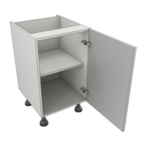
- Page 6 BASE UNIT 500-1000 Sink Hob 1-2 Dr Assembly Guide From Top 94mm Step 11. 126mm Hinge Plates Attach hinge mounting plate onto both end panel or panels,(B) as shown, using Screws which are already positioned within the hinge plates. Hinge side or sides to be mounted in accordance to Customer Specific Kitchen Plan.
- Page 7 Step 12. Insert hinge in top & bottom holes as shown below. Step 13. Secure hinges by tightening 2 x screws with hinge dowels attached. These are already positioned within the hinges. Step 14. Attach the door to unit where required. To attach door, clip hinge onto hinge plate and click to secure.