Table of Contents
Advertisement
Advertisement
Table of Contents

Related Manuals for Titan 125FLAILSHFT


Summary of Contents for Titan 125FLAILSHFT
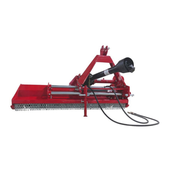
- Page 1 FLAIL SIDE SHIFT MOWER 125FLAILSHFT, 155FLAILSHFT, 185FLAILSHFT 191527, 191528, 191529 Operator’s Manual Read the Operator’s Manual entirely. When you see this symbol, the subsequent instructions and warnings are serious follow without exception. Your life and the lives of others depend on it!
-
Page 2: Important Safety Information
IMPORTANT NOTE BEFORE USE ADD SAE 90 GEAR OIL. DO NOT OVERFLOW. SEE PAGE 17. • Ensure roller weldment is adjusted to proper setting before first use. • Do not engage PTO while adjusting the offset of the mower. • IMPORTANT SAFETY INFORMATION THESE ARE STANDARD PRACTICES THAT MAY NOT APPLY TO THE PRODUCTS DESCRIBED IN THIS MANUAL. -
Page 3: For Your Protection
BE AWARE OF SAFETY ALERT WORDS DANGER: Indicates imminently hazardous practices. A situation that, if not avoided, will result in death or severe injury. The signal word is limited to the most extreme situation, typically for machine components that, for functional purposes, cannot be guarded. WARNING: Indicates a potentially hazardous situation that, if not avoided, could result in death or severe injury, and includes hazards that are exposed when guards remove. -
Page 4: Prepare For Emergencies
Operator’s Manual for additional information. Work in a clean, dry area • Lower the implement to the ground, put the tractor in park, turn off the engine, and • remove the key before maintenance. Allow implement to cool completely. • Do not grease or oil implement while it is in operation. - Page 5 SEFETY LABELS Your flail Mower comes equipped with all safety labels in place. They were designed to help your safety operate your implement. Read and follow their directions.
-
Page 6: Tractor Requirements
INTRODUCTION APPLICATION The Flail Mowers are designed for Category 1, Three-Point Hitch Mounting. These fixed bar Flail Mowers are ideal for ripping, leveling, finish grading, and backfilling applications at outdoor arenas, building sites, and farm and ranch lanes or roadways maintenance operations. SECTION 1: ASSEMBLY AND SET UP TRACTOR REQUIREMENTS This mower is designed with a Category 1, 3 Point Hitch. -
Page 7: Packaging List
PACKAGING LIST THE DETAILED PACKING LIST OF THE MOWER AND ACCESSORY AS THE FOLLOWING TABLE 1. Table 1-1: Packing List of The Mower and Accessory Figure 1-3: Hitch Bracket Weldment and Fittings Table 1-2: Hitch Bracket Weldment and Fittings List... - Page 8 THE DETAILED DESCRIPTION OF SIDE SHIFT SUB-ASSEMBLY AND FITTINGS Figure 1-4: Side Shift Sub-Assembly and Fittings Table 1-3: Side Shift Sub-Assembly and Fittings List THE DETAILED DESCRIPTION OF PTO PROTECTIVE COVER AND FITTINGS Figure 1-5: PTO Protective cover and Fittings Table 1-4: PTO Protective Cover and Fittings List...
-
Page 9: Tool Required
THE DETAILED DESCRIPTION OF BOOT SUB-ASSEMBLY Figure 1-6: Boot Sub-Assembly Table 1-5: Boot Sub-Assembly List ASSEMBLY INSTRUCTIONS The assembly instruction will guide you to finish the final assembly of your new mower easily. TOOL REQUIRED • ½” Ratchet wrench with 19mm sleeve 17-19 Spanner •... - Page 10 Figure 1-7: Installing Boot Sub-Assembly STEP 2: INSTALLING SIDE SHIFT SUB-ASSEMBLY AND FITTINGS Remove the packaging of side shift sub-assembly and fittings. Use 14pc BOLTS M12X40, 28pc PLAIN WASHERS 12, 14pc LOCKNUTS M12 and 7pc BACKING PLATES to fix side shift sub-assembly on the hood panel. TIGHTEN LOCKNUTS COMPLETELY.
- Page 11 NOTE: If the gap shown in figure 1-9 does not meet the hitch bracket weldment installation requirements, remove the oil inlet pipe, and oil outlet pipe to release the pressure in the cylinder. That will make it easy to adjust the gap. Reinstall those oil pipes after hitch bracket weldment installation.
-
Page 12: Tractor Hook-Up
TRACTOR HOOK-UP 1. Be certain that the tractor drawbar will not interfere. Move drawbar ahead or remove if required. The drawbar should also be checked for clearance when the unit is raising for the first time. 2. Align lower link arms of the tractor to hitch clevises on the mower. Insert lower hitch pins into lower ball swivels and attach link pins. -
Page 13: Mowing Instructions
TRANSPORTING NOTE: Always disengage PTO before raising mower to transport position. 1. When raising the mower to transport position, ensure that the driveline does not contact the tractor or mower. Adjust and set tractor drawbar height so the driveline does not reach the mower deck in the fully raised position. -
Page 14: Leveling The Mower
SECTION 3: ADJUSTMENTS LEVELING THE MOWER NOTE: Tractor and mower should be on level ground. Leveling can be adjusted at the tractor draw bars 1. Park tractor and mower on a level ground. 2. Slowly raise mower by tractor draw bars until it is about 1” to 2” above the ground. 3. -
Page 15: Maintenance
SECTION 4: MAINTENANCE MAINTENANCE Proper servicing and adjustment are the key to the long life of any farm implement. With careful and systematic inspection, you can avoid costly maintenance, time, and repair. CAUTION For safety reasons, each maintenance operation must be performed with tractor PTO disengaged, mower lowered completely to ground, and tractor engine shut off with ignition key removed. -
Page 16: V-Belt Installation
V-BELT INSTALLATION 1. Remove belt cover and loose gearbox mounting bracket bolts as well as adjusting bracket bolts. 2. Loose tension bolt and nut to disengage belt tension until belt can be removed. 3. Replace new belt and turn the tension bolt until desired tension is achieved. Retighten tension nut and then retighten tension plate bolts, last retighten gearbox mounting bolts. - Page 17 GEARBOX...
- Page 18 SECTION 5: SPECIFICATIONS AND CAPACITIES SECTION 6: TROUBLESHOOTING...
-
Page 20: Bolt Torque
BOLT TORQUE The tables shown below give correct torque values for various bolts and cap screws. Tighten all bolts to the torques specified unless otherwise noted. Check tightness of bolts periodically, using bolt torque chart as a guide. Replace hardware with the same strength bolt. - Page 21 PARTS DIAGRAM / EXPLODED VIEW...
- Page 24 Titan, its insurers, employees, officers, directors, associates, and agents from any and all claims, demands, damages, rights of action, or causes of action, present or future, whether the same be known or unknown, anticipated, or unanticipated, resulting from or arising out of the use of said equipment.
- Page 25 NEED HELP? CONTACT US FIRST. 1-800-605-7595 info@palletworks.com www.palletforks.com © 2021 Titan Brands...
Need help?
Do you have a question about the 125FLAILSHFT and is the answer not in the manual?
Questions and answers